The Create Isochrones function works on points selected when the function is invoked.
Select the overlay points.
Select Create Isochrones.
Note: If no points are selected the following message will be displayed:
The Isochrones dialog will be displayed:
To create an isochrone it is necessary to specify the travel limit – this is done in the context of the measurement option. In the above dialog three isochrones are to be created at time limits of 4, 8 and 12.
The measurement option ITN Road Speed expression is selected, this is specifying 4 minute, 8 minute and 12 minute isochrones based on the speeds defined in the settings dialog, e.g. 4 minutes at 60mph on Motorways, 30mph on A Roads, etc. and 8 minutes at these speeds and 12 minutes at these speeds.
See the example below:
Two overlays are required:
One overlay containing the ITN network, in this example 54194-ST1010-25c155.gz
One overlay containing the features defining the locations from where the isochrones are to be calculated. The function will create an isochrone about every item selected when it is invoked, in this example the overlay Depots is used.
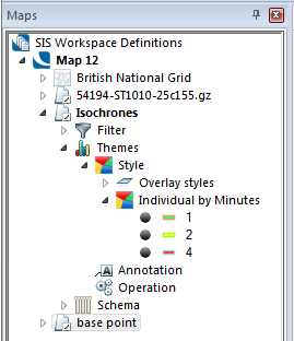
Isochrones are created in a new overlay, called Isochrones, and are displayed in the overlay’s default style:
A theme can then be applied to clearly show the individual isochrones:
Key points regarding isochrones
When specifying multiple isochrones, e.g. 5 10 15, the Time Limit values must be separated by a single space:
The Buffer Distance (metres) parameter defines how large a buffer is drawn around the routes which can be travelled in the specified limits. If Buffer Distance (metres) is set to 0 then no buffer will be created, i.e. the command will create Iso-routes (Iso-routes contain just lines representing the routes which can be travelled in the specified limits) rather than Isochrones.
By default Isochrones are created as QZones; these are fast to create. The Buffer Resolution is the cell size of the QZone. By changing the Buffer Resolution value you can alter how ‘blocky’ the QZones will be.
Note: When entering a value in the Buffer Distance (metres) box to ensure the Buffer Resolution value is correctly updated either use the tab key or click either in the box, or another part of the dialog to activate the buffer resolution and ensure the value registers. If this is not done it is possible that an incorrect resolution could be applied, this could even result in a different type of buffer.
Entering a Buffer Resolution of 0 will cause smooth Polygon items to be created instead of QZones. These are significantly slower to create.
Isochrones are calculated using the links in the network. If the selected points are not on the links then their positions will be ‘snapped’ to the nearest link. The maximum amount by which a point can be snapped is defined by the number entered in the Snap Radius (metres) parameter of the Isochrones dialog. This can be made as large as you like but if you find yourself entering a large number you should consider adjusting the points being used so that they are closer to the network, i.e. if the Snap Radius is very large can you be confident that the snap is to the ‘correct’ location?
In the first screen shot below you can see ‘holes’ in the isochrones, i.e. ‘captured’ areas which are further than the buffer distance away from the network. Checking the Fill isochrones tickbox will create isochrones with these holes filled, see the second screen shot.
Note: Checking the Fill isochrones tickbox will result in the isochrones being created as Polygons instead of QZones and these are significantly slower to create.
With the Fill isochrones tickbox unchecked:
With the Fill isochrones tickbox checked:
Intersect areas are the areas where all the isochrones for an individual travel limit intersect. Generally this is most useful where there are only a small number of isochrones, e.g. areas reached from just two or three points.
Example of Intersect areas from two points (blue crosses) and themed by Minutes.
To aid in creating themes, the isochrones or iso-routes created by this command are set with different draw levels. The level is set so that isochrones for the first Travel Limit value supplied will appear as the top-most isochrones and those created for subsequent Travel Limits will appear progressively lower.
For example, taking the Travel Limit (Minutes) themed in the above figure, the 4 minute isochrones will be the lowest (level 1), the 2 minute isochrones will sit on top of these (at level 2) and the 1 minute isochrones will be on top (at level 3).
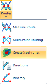 Create Isochrones
 selected.gif)
.png)
.png)
.png)
.png)
.png)
.png)