Draping over 3D data
Draping is projecting 2D data onto 3D data. Draping raster images is like stretching a sheet of rubber onto a 3D surface.
Cadcorp SIS Desktop can drape both raster images and vector graphics over 3D models.
Draping a Raster Image onto a Grid or TIN
Cadcorp SIS Desktop can drape a raster image onto 3D data, i.e. onto Grid items and TIN items.
Draping raster images requires a significant amount of memory; ensure you do this processing on a high specification workstation if possible with a high specification graphics card.
Draping a Raster Image onto a Grid - example
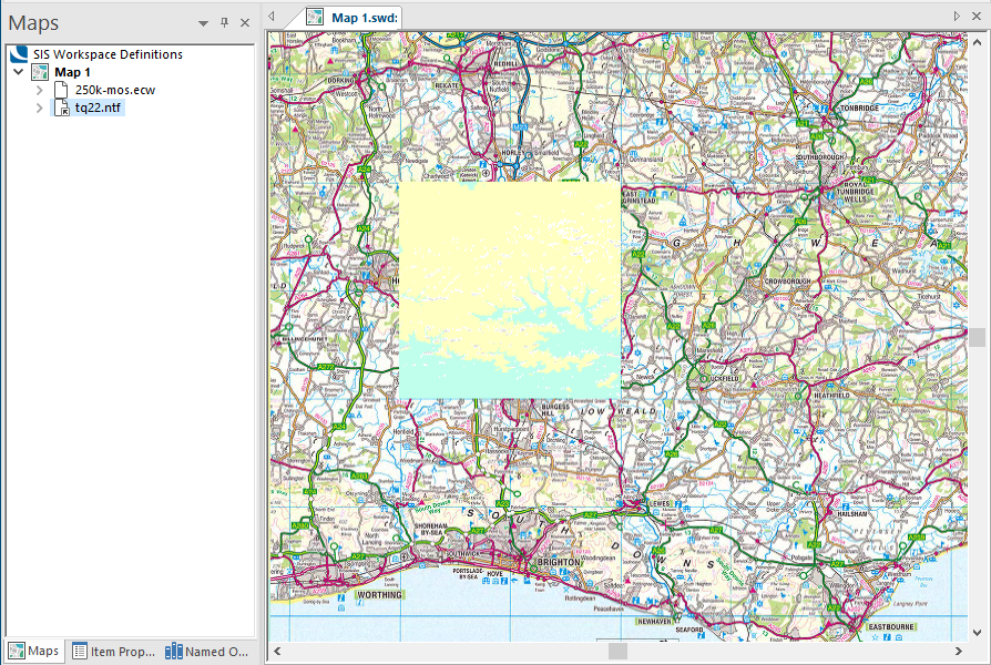
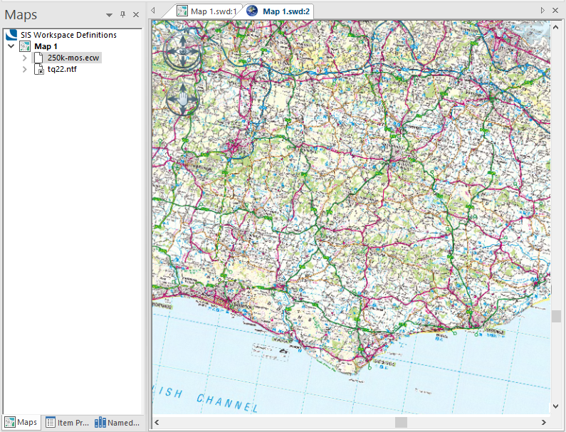
This example takes a Grid, Tq22.NTF and drapes it with 250k-mos.ecw.
Open a SIS Workspace Definition (SWD) and load the overlays 250k-mos.ecw and Tq22.NTF:
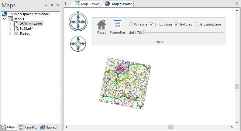
Click View > 3D.
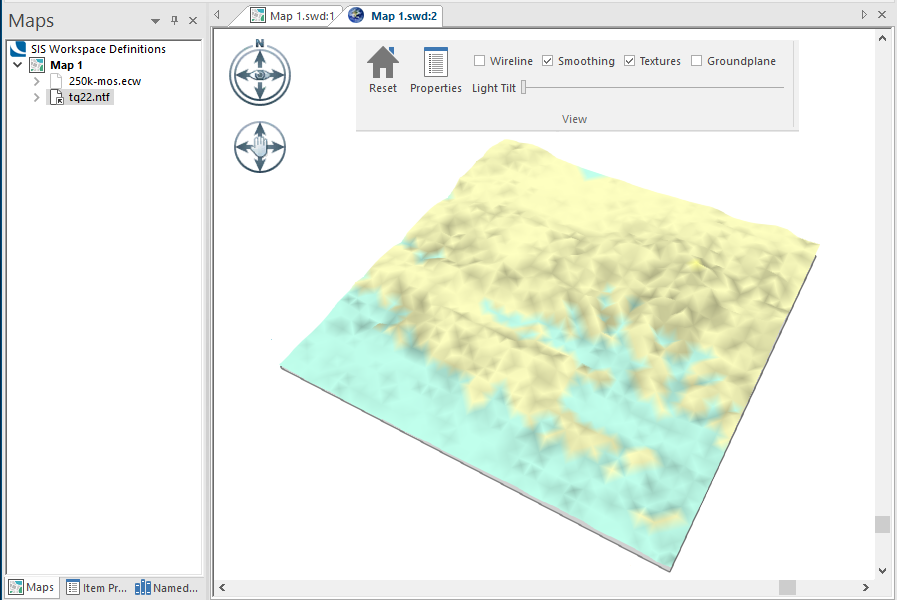
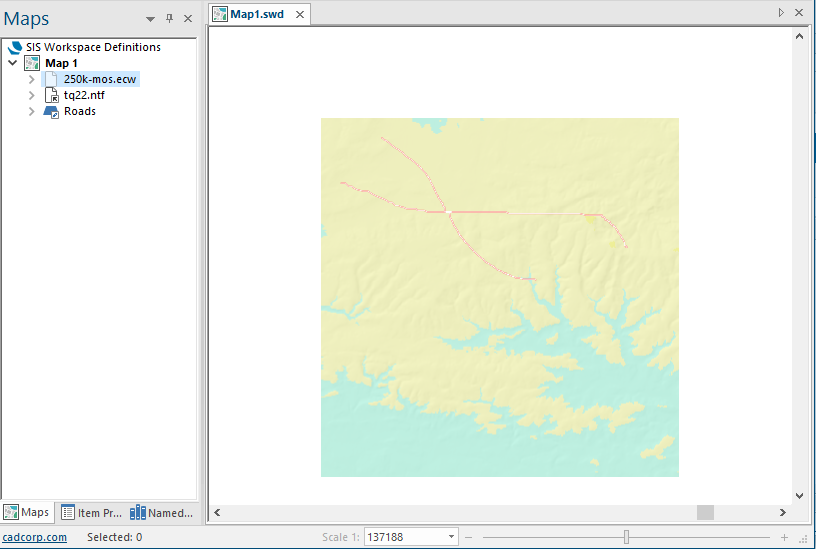
With the Wireline tickbox unchecked and the 250k-mos.ecw overlay set to Invisible, the view looks like this:
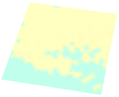
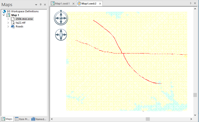
With the Wireline tickbox checked the view looks like this:
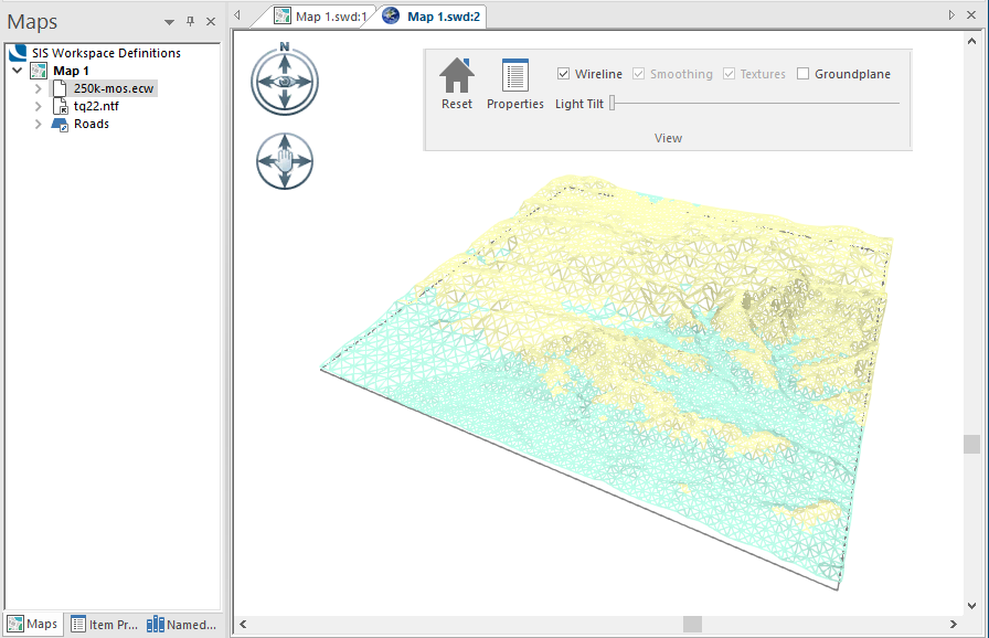
Checking the Wireline tickbox will speed up the 3D processing.
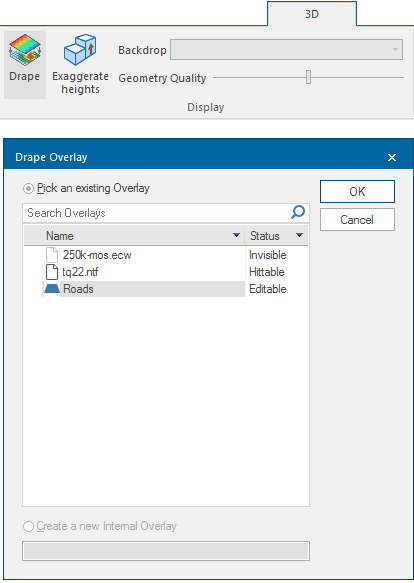
Click Drape (3D > Display) and select 250k-mos.ecw from the Drape Overlay dialog:
Note: The Drape button will be disabled if your computer is using a DirectX 9 level graphics card.
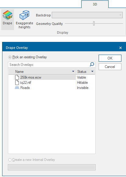
Note: The Create a new Internal Overlay option is not available as it has no function in this operation.
Click OK.
The 3D Window display will now show the Drape Overlay:
It may not be possible to see the Tq22.NT overlay that has been draped at this stage.
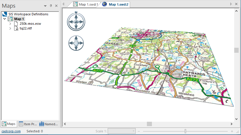
Uncheck the Groundplane tickbox, the 3D window will now only show the draped area of Tq22.NTF:
The Textures tickbox should be checked. If left unchecked the display will show just the Grid.
The 3D view can be manipulated using a combination of the Look joystick, the Move joystick, the Slider bar and mouse movement with the left-button or the wheel button held down.
TIP: See Working in a 3D Window for more information on the 3D Window controls.
The Exaggerate heights control can be used to enhance the height values so the terrain can be better visualised; enter a suitable value in the Exaggeration factor dialog:
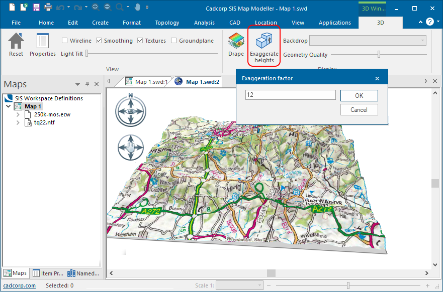
The 3D view can be manipulated using a combination of the Look joystick and the Move joystick to the left of the 3D window, the Slider bar at the bottom of the 3D Window and mouse wheel and button operations as follows:
Roll the mouse wheel back and forward to zoom in and out.
Hold down the mouse left button and move the mouse up and down and left and right to pan the view.
Hold down the mouse wheel and move the mouse up and down to tilt the view, move the mouse left and right to rotate.
Draping LineStrings onto a Grid or TIN
Cadcorp SIS Desktop can drape LineString items over the surface of a Grid or TIN items
This command moves the vertices of the LineString items up or down so that they lie on the surface of the TIN. In addition, wherever the LineString item crosses a TIN triangle, a 3D vertex is added to the LineString item at the edge of the triangle.
The LineString items must be on an editable overlay and must lie totally inside the TIN.
See the following example of draping a LineString onto a Grid.
Draping LineStrings onto a Grid - example
This example takes a Grid, Tq22.NTF and drapes it with a LineString in an overlay called Roads.
The LineString items must be on an editable overlay and must lie totally inside the Grid or TIN as there are no known height values outside the Grid or TIN.
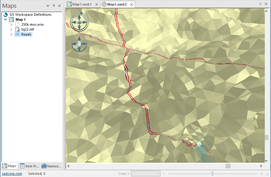
Open an SWD and load the overlays 250k-mos.ecw and Tq22.NTF and create an overlay called Roads containing LineString items:
Click 3D Window [View-Document Views]
With the Wireline tickbox checked the view would be similar to:
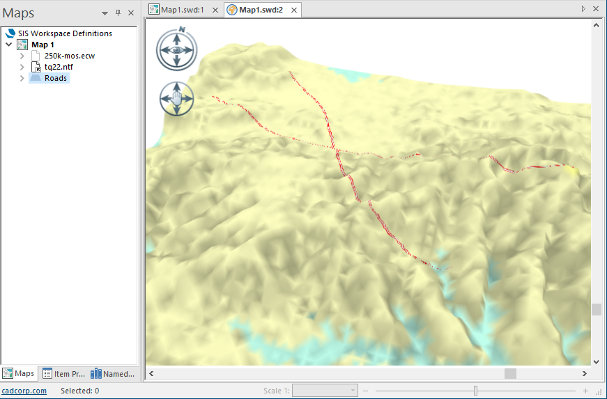
Click Drape [3D-Display] and select Roads from the Drape Overlay dialog:
Note: The Create a new Internal Overlay option is not available as it has no function in this operation.
Click OK.
The 3D Window display will now show the Roads overlay:
The 3D view can be manipulated using a combination of the Look joystick and the Move joystick to the left of the 3D window, the Slider bar at the bottom of the 3D Window, and mouse wheel and button operations as described above.
The Exaggerate heights control can be used to enhance the height values so the terrain can be better visualised, click the Exaggerate heights button and enter a suitable value in the Exaggeration factor dialog.