CAD tools - an overview
The CAD tool options bring you the best of CAD and GIS convergence.
You can use these tools for many CAD-related functions (eg draw the outline of buildings on Map, use the rectangular array for carparks, for survey work, etc).
Take a look at the example below to see these tools in action.
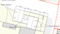
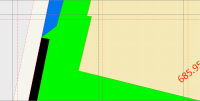
Here we have a building:
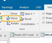
To find the dimensions, use CAD > Axes Move.
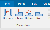
Align it to the building with two snaps. Now you can begin using the dimension tools.
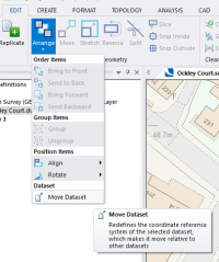
If you get a non-georeference CAD file (eg DXF) use Move Dataset (Edit > Geometry > Arrange). Load the data and split the screen.
Draw a line in the Y axis and use Measurement to find the angle of rotation.
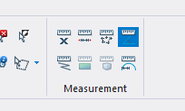
Select all the data in the DWG overlay and click Edit > Geometry > Arrange > Move Dataset.
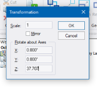
Select a position to move from (snap in the DWG overlay), press return and enter the rotation.
Snap in the mastermap to locate the DWG; now do another slight rotation.
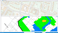
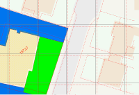
This is the location that has been moved and rotated; you can see it spot on (the speckle hatch is the selected building, the red dash is the DWG)
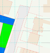
The Black lines are 10m National Grid, the red dash is the 10m grid in the DWG. As we move diagonally to the top right, the shift is greater.
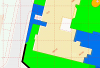
A final move to align the girds gives this in the top right.
But in the bottom of course we get a shift
For Divide, here is the carpark example. The rectangle below can be split into 10 parking bays.
Select Divide Distance and enter the number required.
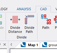
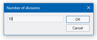
Click Left to right followed by Up and down. Your rectangle will now resemble this:
At the moment these are all just lines. For polygons, select all the lines.
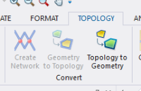
Then on the Topology tab press Geometry to Topology.
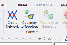
Now we have “links”. On the Topology Tab select From LineString.
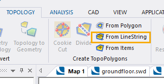
Snap to the left and right outside the parking bays. Hit return.
Now we have polygons.
Select these Topo polygons and press Topology to geometry
Now we have 10 individual polygons to manipulate and handle.

