Rubber Sheeting Vector (Fitted Linear)
First import your image file using Add Overlay > Files > Imported File.![]() Related Topics
Related Topics
The image will be placed at coordinates 0, 0 unless if it is georeferenced.
TIP: Use split view with View > Window > Split Vertically and zoom in to the area where the image is in one view, and the area where it needs to be placed in the other.
The next step in creating a rubber-sheeting transformation on a vector image is to create Displacement lines.![]() Related Topics
Related Topics
You cannot draw the lines within the Process dialog. However if you know the From and To X, Y coordinates, you could enter these in the Process dialog.
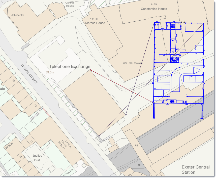
Draw a line between the parts of the imported image that match the OS Mastermap overlay.
For example in this setup: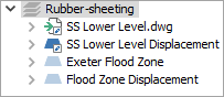
- Switch on the SS Lower Level.dwg overlay
- Right-click the SS Lower Level Displacement overlay and click Make Current
- Set the OS Mastermap overlay to hittable
- From the Create ribbon tab, click the Displacement option in the Miscellaneous group
Set (a minimum) of 3 x displacement lines - with vectors such as this it is easiest to use the corners of the shapes.
Next create the Rubber-sheeting. To do this select Create > Process.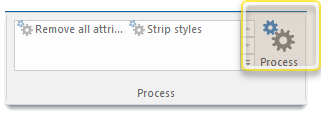
This opens the Processing input window: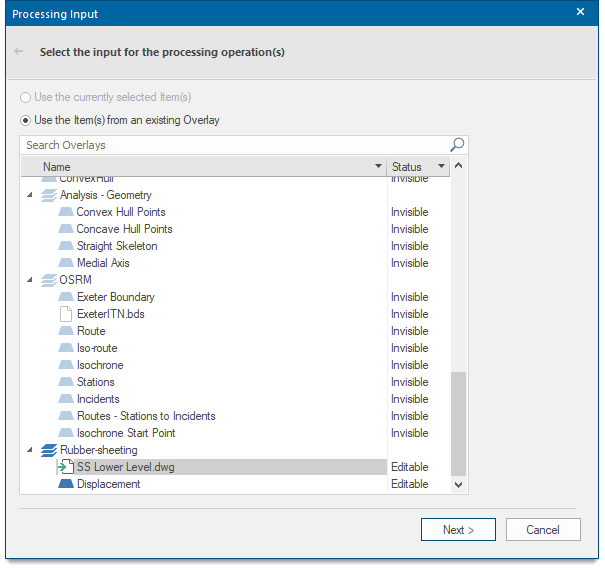
Select the SS Lower Level.dwg from the list and click Next. This opens the Processing Operations dialog.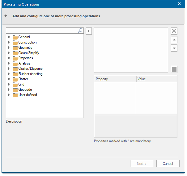
Expand the Rubber-sheeting folder.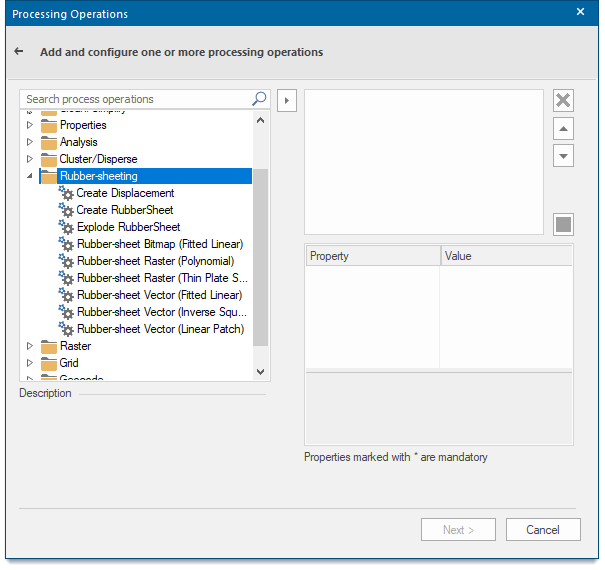
As you are fitting a vector layer (dwg) against an OS Mastermap vector layer, select the Rubber-sheet Vector (Fitted Linear) by double-clicking it.
The process is placed in the upper-right panel and some properties are displayed below. Select the Overlay property.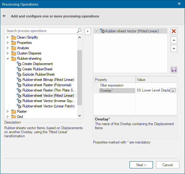
Select the Value drop-down list and select the SS Lower Level Displacement overlay and click Next.
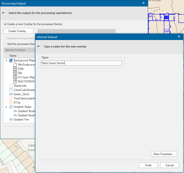
This in turn opens the Processing Output window:
- Click the Create Overlay button
- Select New Internal Dataset.
- Click Next.
- Name the overlay (e.g. Fitted Linear Vector)

-
Click Finish.
-
Click Finish again to complete the process.
The rotated .dwg image will display as a linear fit to the OS Mastermap object.