Creating a Topological Road Network
This example explains the processes involved in creating the topology of a fictitious road network. It will step through creating the Link and Node primitives editing and adding to the network and defining logical rules such as turning restrictions and one-way streets.
The example is intended to introduce all the relevant topology methods available in Cadcorp SIS Desktop including the settings which can affect the way the topology is created.
Constructing a Network of Links and Nodes
You can construct a topological network by drawing the linework as Links then placing Nodes at the intersections of Links where required. This method is labour-intensive but gives a greater degree of control over the network.
Select Link (Topology > Build) and draw the link just as you would draw a LineString item.
Note: When drawing Links you do not have options to trace existing LineString items or force orthogonal LineString items.
Links have editing handles at their ends and vertices (similar to a normal LineString item). You will find that a Node has been created at each end of the Link as a Link cannot exist without starting and ending at a Node.
Now construct two more Links:
Each of these three Links will have Nodes at their ends.
Nodes are not created automatically at the intersections where Links cross. Before you can manually place a Node at an intersection you will need to change the Automatic property of the Links to True. This allows the Links to be automatically split at the Node position to form a fully connected network:
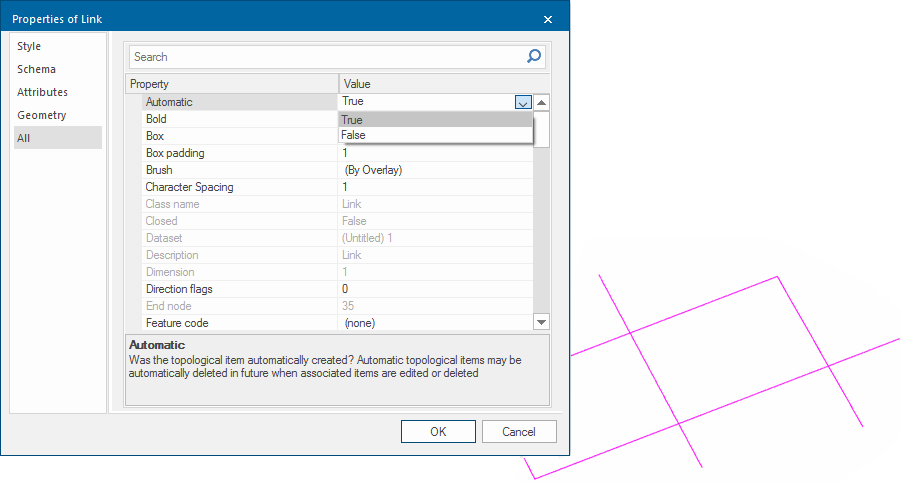
Now select Node (Topology > Build) and place Nodes at the four intersections.
If the Automatic property is not set, you will see this message when you attempt to add a Node:

Why would you want to change the Automatic property of a Link?
In the example above it has been assumed the road network will have intersections wherever Links cross. In a real network however the Links may represent roads that cross at different levels yet do not intersect.
When merging linework into an existing topological network, the Automatic property helps determine if Nodes should be automatically inserted at intersections of existing Links.
A quicker way to create Topology
Creating a network by drawing each Link and inserting each Node is time-consuming. In most cases it is much easier to have the network automatically generated from simple LineStrings.
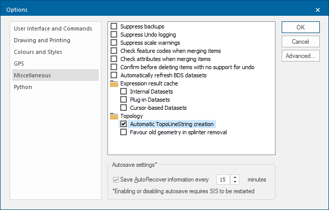
Before doing this look at the Automatic TopoLineString creation setting in the Topology section of the Miscellaneous tab of the Options dialog.
TopoLineStrings are constructs which represent routes made of a series of Links.
To create a topological network from existing simple LineString items, first decide if you want the original LineStrings to be “retained” as TopoLineStrings. The network will be created as Links and Nodes with each original LineString being broken into separate Links. They will be connected by Nodes at each junction.
If the original linework holds attributes such as RoadName, Classification, etc. this attribution will not be carried over to the Links and the original linework and attribution is lost.
If you select Automatic TopoLineString creation, a TopoLineString item is created for each original LineString item with the attribution retained.
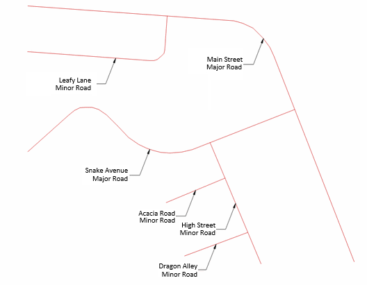
An example of part of a road network is shown below. It is drawn using simple LineString items. The attributes held on each LineString item are shown by a Label Theme.
- Make sure Automatic TopoLineString creation is checked in the Topology tab of the Options dialog.
- Select Geometry to Topology (Topology > Convert). The appearance of the road network does not change but each LineString item, e.g. Snake Avenue, has been split into Links, with Nodes inserted at the ends. In this example Snake Avenue is split into 2 Links. These Links do not retain any attributes from the original Snake Avenue; however a new item a TopoLineString is also created. This new item has no geometry of its own but is simply a reference to the Item IDs of the Links.
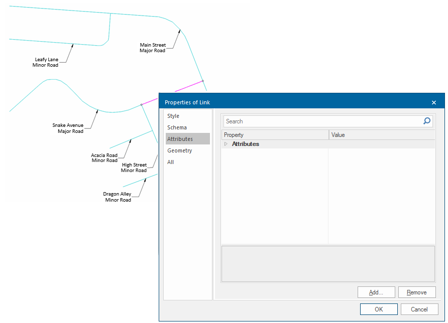
- Click on Snake Avenue to select it. You will see that you have selected a Link. Display the properties of the Link and you will see that it does not hold any attributes:
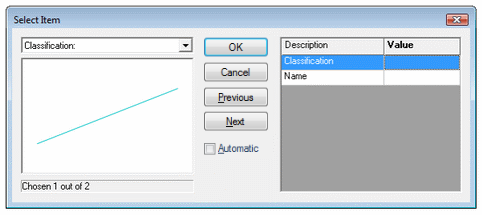
Hover the mouse pointer over Snake Avenue and press the S key on the keyboard (S = Select). The Select Item dialog will be displayed showing two items present.
Item 1:
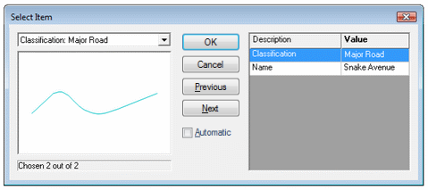
Item 2:
This is how you can use Geometry to Topology [Topology > Convert] to quickly create a topological network from simple LineString data. This way the “logic” of the original is preserved while at the same time reaping all the benefits of topology.
Note: If your original linework does not hold any useful attribution, ensure Automatic TopoLineString creation is un-checked in Options > Topology. This will create a network of Links and Nodes without preserving the original structure of LineString items.