Example 2 - Creating a style for Land Registry Inspire Polygons.
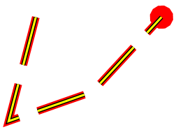
This example shows how to create a multi-level Pen to produce the following LineString item:
Create a LineString or Polygon Item.
Select the Item and select the local (right-button) Properties command.
In the Properties of LineString or Properties of Polygon dialog select the Style tab and click the Pen down-arrow. Click the right arrow at the bottom of the Pen drop-down to display the Edit Pen dialog.
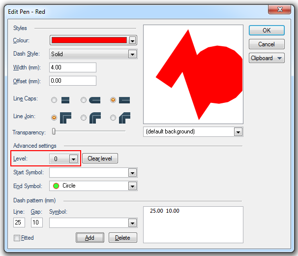
Enter the following settings for Advanced settings - Level 0:
Change the Advanced settings to Level 1 and enter the settings as shown:
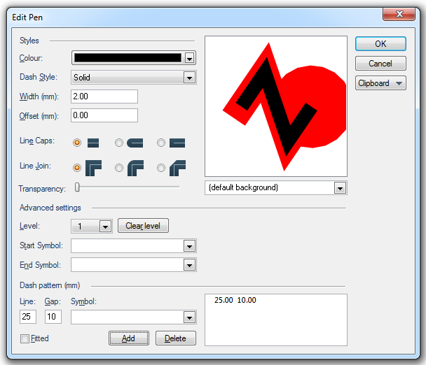
The two levels of the pen settings will now appear as above.
Change the Advanced settings to Level 2 and enter the settings as shown:
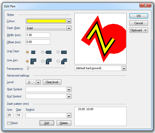
The complete multi-level, Level 0, Level 1 and Level 2, pen settings will now appear as above.
The above Edit Pen dialog settings would create a multi-level Pen that will produce the following multi-level LineString:
The JSON for this multi-level Pen is as follows:
{"Pen":[
{"Pen":{"Colour":{"RGBA":[255,0,0,0]},"Width":400,"Symbols":{"End":"Circle"},"Patterns":{"Fitted":false,"Repeats":[{"Line":2500,"Gap":1000}]}}},
{"Pen":{"Colour":{"RGBA":[0,0,0,0]},"Width":200,"Patterns":{"Fitted":false,"Repeats":[{"Line":2500,"Gap":1000}]}}},
{"Pen":{"Colour":{"RGBA":[255,255,0,0]},"Width":100,"Patterns":{"Fitted":false,"Repeats":[{"Line":2500,"Gap":1000}]}}}]}
Note: The JSON can be copied using Clipboard - Copy as JSON and edited in a JSON editor, see Clipboard - Cut & Paste.
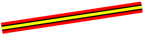
Take the above multi-level pen and remove the end symbol in Level 0, remove the dash patterns from all levels, increase the Width of the line in all levels. The modified multi-level pen would now produce the following LineString.
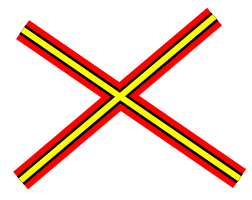
Where these LineString Items cross they will appear as:
The JSON would now be as follows:
{"Pen":
[{"Pen":{"Colour":{"RGBA":[255,0,0,0]},"Width":800}},
{"Pen":{"Colour":{"RGBA":[0,0,0,0]},"Width":400}},
{"Pen":{"Colour":{"RGBA":[255,255,0,0]},"Width":200}}]}
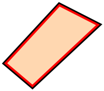
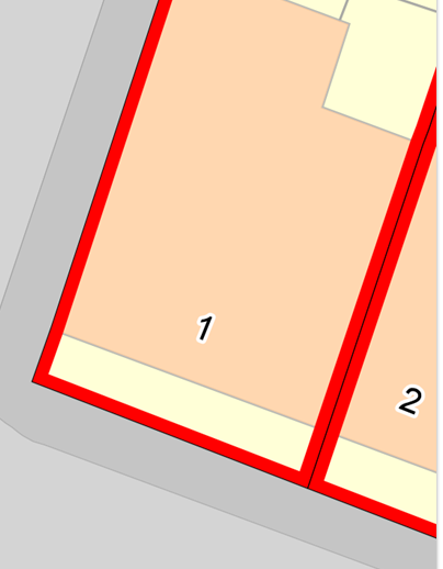
This example shows how you can create and generate a style for Land Registry Inspire Polygons.
The style will have a black line to define the edge of the Polygon and a red line to define the inside:
Select Overlays [Home-Map] or press F2 to display the Overlays dialog.
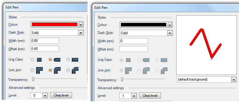
In the Overlays dialog Styles tab select the Pen drop-down arrow. Click the right arrow at the bottom of the Pen drop-down to display the Edit Pen dialog.
For Level 0 enter a width of 0.8 and an offset of 0.4 (half the width) to enable the style to appear inside the edge of the Polygon.
For Level 1 just select the default black line, with zero width.
When you click OK and return to the map you will see the lines similar to the following:
Note: You may need to set the scale override for the overlay to see the styling.
When you offset your styling you may find that it appears on the outside of the Polygon rather than the inside (left image below). This occurs when features were captured in both clockwise and anti-clockwise directions.
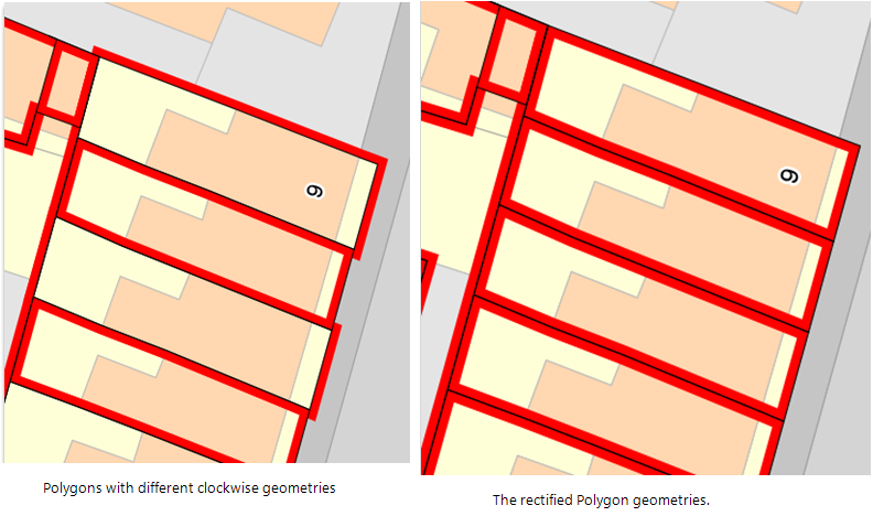
For a small number of Items you can rectify this by selecting the affected Items and clicking on Reverse [Edit-Geometry].
If there are too many features to rectify manually you can use an expression to select them all.
Clockwise (_bClockwise&) is a system property in SIS which informs you of the clockwise (or anti-clockwise) geometry of an Item.
Select .gif) Find [Home-Selection] or Ctrl+F in the Map Window to display the Find dialog.
Find [Home-Selection] or Ctrl+F in the Map Window to display the Find dialog.
Select the Expression tab and enter the expression:
_bClockwise&=True
Click OK.
All Items with the _bClockwise& property set to True will be selected.
With the Items still selected click on Reverse [Edit-Geometry].
Send comments on this topic.
Click to return to www.cadcorp.com
© Copyright 2000-2017 Computer Aided Development Corporation Limited (Cadcorp).