LineString
A LineString item is made up of vectors (LineString segments), each vector having a vertex point at its beginning and its end.
LineString items can consist either of just a single segment or a series of connected segments (known as a MultiLineString item).
- A LineString item can have curved segments and can be open or closed. Straight lines, arcs and curves are all examples of LineString items.
- LineString items can also be 3D LineString items, i.e. their coordinates can lie in three-dimensional space.
To create a LineString:
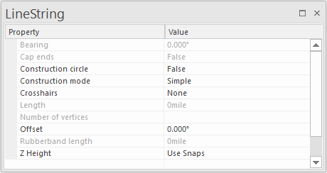
This dialog remains open allowing you to edit LineString parameters even during usage.
Note: A Freehand LineString item is created by placing vertices at short time intervals. See also Freehand.
The bearing is displayed in the in the Bearing - Value field as the LineString is created. The bearing from the last snapped position is also displayed in the Status Bar, eg:
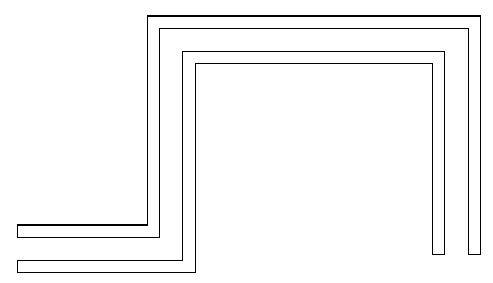
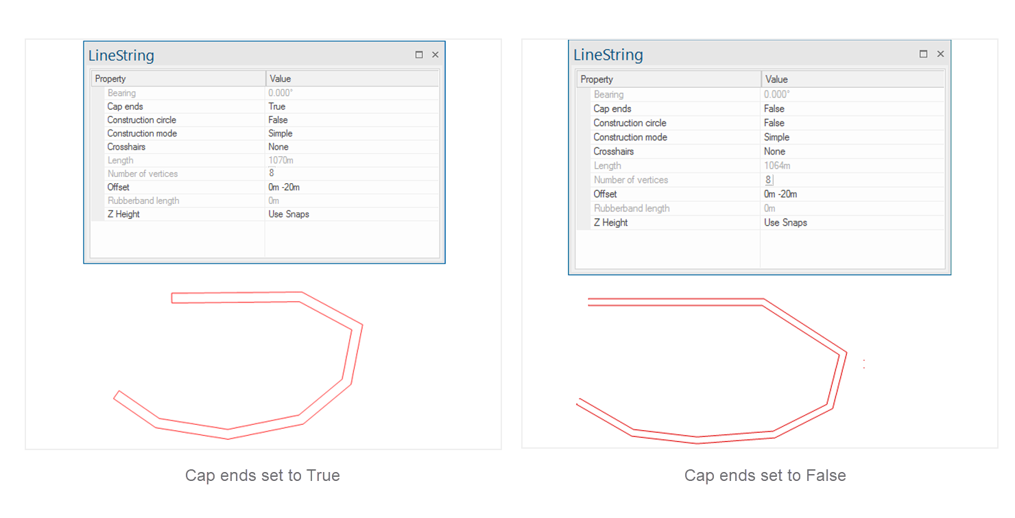
Caps the ends of pairs of LineString items when using multiple offsets, eg to draw a wall. See also Offset.
.png)
Displays a construction circle centered on the mouse start point with the last snapped position on the circle, eg: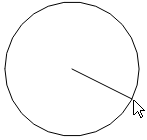
Choose True or False to enable or disable this option. The construction cicle is just construction geometry and is purely to assist in drawing the line string.
Construction mode
Affects how snapped or typed positions are interpreted and also the offset from those positions from which to create the LineString item. You can freely switch between these modes during LineString item construction. Choose a mode from the drop-down menu.
.png)
1. Simple
In this mode, you can specify the start position of the LineString item by snapping to a position on the screen or typing a coordinate. Now keep adding points (by snaps or coordinates); each time a LineString item segment will be drawn to the new position.
Press Enter or double-click to finish the LineString item. Press Ctrl + Enter if you have drawn a LineString item of 2 or more segments and wish to close the LineString item back to the first point (effectively creating a closed LineString item).
Press Backspace to remove a point. Each subsequent press of the Backspace key will backtrack through the previous points.
2. Trace
This mode constructs a LineString item by tracing over existing graphics.
Tracing over base data is simple and reliable in Cadcorp SIS Desktop 9.1 when used in conjunction with pan and zoom and ability to display more than one view of the map.
Snap or type a position for the start of the trace (ideally choose a vertex on the geometry to be traced) and snap a position to trace to.
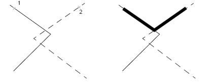
To search for a continuous path between the first and second point, click over existing geometry. The trace will follow exactly over the path of the geometry being traced, irrespective of how many intermediate vertices it contains.
- The trace sequence is drawn on screen using a thick outline. Press Backspace to return to the previous trace point, or Shift+Backspace to step back over the vertices of the last intermediate trace sequence.
- The trace path will not jump between different bits of geometry. To do this, navigate to the intersection between two pieces of geometry.
- To trace over an existing geometry completely, click the first point. Now hold the CTRL key down and click anywhere along the geometry to be traced close to the first point in the direction you wish to trace. SIS will not insert a vertex at this point but will attempt to trace the geometry right to its end (no matter how long or how many intermediate vertices are needed).
- You can also enter a position while holding the Shift key and jump directly to the position you create; this NEED NOT be on existing geometry.
- If the start and end positions of a trace segment are on topological Link items, SIS will automatically perform a topological route-find using a shortest-route algorithm.
- Press the Enter key to accept the trace sequence or press Ctrl+Enter to close the shape, joining the last point back to the first. A LineString item will be created along the traced path.
REMEMBER when tracing external map data
- Vector-based maps such as those supplied by Ordnance Survey have been created by digitising existing paper maps. These paper maps are supplied in tiles. Where a feature such as a road centreline or road edge comes to the edge of one of these map tiles, the graphics stop and start again on the adjacent map. The digitised line may therefore stop at an unexpected place.
- The person digitizing the original data may have stopped the line at a position which seemed appropriate, but may not suit your requirements.
- Graphics may have been digitized using many points resulting in multiple vertices.
3. Find route
SIS Desktop will automatically look for a route between entered positions. The route can be made up of geometry from any item. If your positions are far apart, then SIS may spend some time looking for a route.
By clicking on two points on an existing LineString item or on two overlying LineString items, the shortest route between these two points is calculated and a LineString item constructed along this route.
This feature is useful when used with link and node network. Here it will respect flow directions assigned to links and turning rules applied at nodes (junctions).
You can also use Point-to-point analysis to create new LineString items that follow routes.
4. Orthogonal
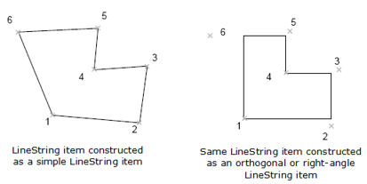
All LineString item segments will be corrected to be parallel to the X and Y-axes, giving right-angled corners. To draw LineString items at angles other than 0, 90, 180 and 270 degrees, remember to change the orientation of the axes . See also Rotate.
5. Right angles
In this mode, each LineString item segment will be created at right-angles to the previous segment.

Displays a cross hair at the start and end of the construction of a LineString item. This is particularly useful for CAD functionality. Sizes available are small, medium, large or full. A full crosshair covers the length and breadth of the entire map window.
These are information fields; they show the total length of the completed LineString item and the number of vertices.
LineString items can also be created between two chosen points with a specified offset distance.
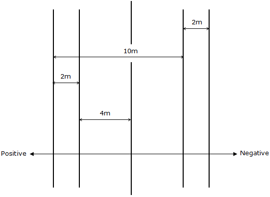
- To create a single offset LineString item, enter the offset distance (in meters) and press Enter. Positive offsets are placed to the left (looking along the LineString item in the direction in which it is drawn) and negative offsets to the right.

- To create multiple offset LineString items, enter a series of offsets (separated by a space), and press Enter.
- If you are constructing multiple offset LineString items with regular spacing, you can use REP, R or r to repeat an offset. For example, to draw a simple LineString item and then create 6 further copies 10 metres apart, enter 0 10 R 6.
-
With multiple offset LineString items, you can choose whether or not to cap the ends. If you do, set the Cap ends option to True then pairs of LineString items are joined:
Note: Each subsequent offset is measured relative to the previous one. For example, you were to draw a simple LineString item from the bottom of the screen to the top, using the offsets 0m 4m 2m –10m –2m, the result would be:
Examples of Offset LineString items
If 0 is entered as the first value the LineString item will be created with the cursor at the bottom of the LineString item:
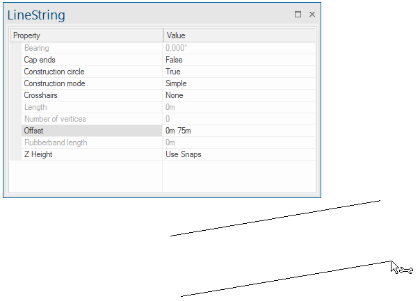
If a negative value is entered as the first value the LineString item will be created with the cursor at the specified offset from the bottom of the LineString:
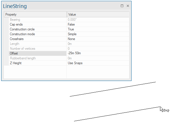
This is an information field showing the dynamic length of the line that will rubberband from the end of the LineString item being drawn.
You can enter a value here to override the height of each snap with a fixed value.
See also Creating LineString items and Editing LineString items.

