Create Isochrones
The Create Isochrones function works on points selected when the function is invoked.
See here  for more information on isochrones.
Select the overlay points.
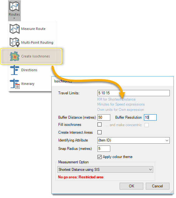
Select Applications > Routes > Create Isochrones.
Specify Travel Limits to begin creating an isochrone (separate multiple limits with a single space).
In the above example, three isochrones are created at time limits of 5, 10 and 15.
If you select ITN Road Speed expression as your measurement option, this will specify 5 minute, 10 minute and 15 minute isochrones based on the speeds defined in settings, (e.g. 5 minutes at 60mph on Motorways, 10 minutes at 30mph on A Roads, etc).
Buffer Distance (metres) defines how large a buffer is drawn around the routes. Set to 0 if you don’t need a buffer.
Note: Without a buffer isoroutes will be created instead of isochrones.
By default Isochrones are created as QZones  ; the Buffer Resolution is simply the cell size of the QZone.
Change the Buffer Resolution to alter how thick or ‘blocky’ the QZones will be.
A Buffer Resolution of 0 will create smooth Polygon items instead of QZones.
In the first image below you can see ‘holes’ in the isochrones, i.e. ‘captured’ areas which are further than the buffer distance away from the network.
Tick the Fill isochrones checkbox to create a more organic shape.
Note: Enabling Fill isochrones will create isochrones as Polygons instead of QZones; be aware however Polygons are significantly slower to create.
With the Fill isochrones tickbox unchecked:
Select the identifying attribute from the drop-down menu. These attributes are inherited from the currently active overlay.
“Identifying Attribute” allows an attribute to be selected from the points’ overlay schema (or the item id) to be included as an attribute of isochrones.
This means there is a way of identifying which point it was based on. This attribute will appear in the schema of the isochrone’s overlay.
Isochrones are calculated using the links in the network. If the selected points are not on the links, their positions will be ‘snapped’ to the nearest link.
Snap Radius (metres) defines the maximum amount by which a point can be snapped.
The Snap Radius value has no upper limit but if using a large number, consider adjusting the points being used so they are closer to the network. If the value is very large, it can be difficult to ascertain if the snap is to the ‘correct’ location.
Select one of the measurement options from the drop-down menu.
If the selected measurement option is a speed-based one, travel limits can be specified in mm:ss format, e.g. 2.5 or 2:30 for 2½ minutes.
See the example below:
Two overlays are required:
- One overlay containing the OS Highways network, in this example 54194-ST1010-25c155.gz
- One overlay containing the features defining the locations from where the isochrones are to be calculated. The function will create an isochrone about every item selected when it is invoked, in this example the overlay Depots is used.
.png)
- Isochrones are created in a new overlay called Isochrones and are displayed in the overlay’s default style:
.png)
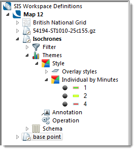
A theme can then be applied to clearly show the individual isochrones:.png)
To help in creating themes, the isochrones or iso-routes created by this command are set with different draw levels.
The level is set so that isochrones for the first Travel Limit value supplied will appear as the top-most isochrones and those created for subsequent Travel Limits will appear progressively lower.
For example taking the Travel Limit (Minutes) themed in the above figure, the 4 minute isochrones will be the lowest (level 1), the 2 minute isochrones will sit on top of these (at level 2) and the 1 minute isochrones will be on top (at level 3).

.png)
.png)
.png)