Constructing Dimensions
Dimensions are constructed on the current overlay or, if there is no current overlay, on the first editable overlay (creating one if necessary). Once created, dimensions can be edited. See Editing LineString items.
The dimensioning commands offer four ways of dimensioning graphics automatically. You can dimension any graphics as long as they have a status of hittable or editable. see The Overlays dialog for an explanation of these terms.
With the exception of Distance [CAD-Dimension], these commands create their dimensions so that the dimension line is parallel to the X axis. If you want dimension lines at a different angle, rotate the axes first.
Dimension can be edited, once drawn, by selecting the dimension item and accessing its properties from the local Properties... command.
These commands are not available in Map Manager.
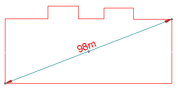
Distance [CAD-Dimension] - Constructs a simple linear dimension between two points.
This command creates a single dimension between two points. The dimension line takes no account of the current X axis, but is drawn directly between the two points chosen.
- Select Distance [CAD-Dimension].
- In the Distance Dimension dialog:
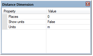
select the units to be used, the precision required (Places) and whether to show the units on the dimensions.
- Click the two points between which you want to dimension. If you make a mistake inputting a point, press the Backspace key to remove it.
Back to top of page
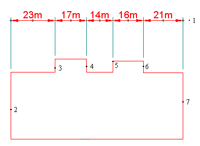
Chain [CAD-Dimension] - Constructs a chain dimension along a line that is parallel to the X axis.
This command allows you to dimension between any number of points, the distance to each point being measured relative to the last.
- Select Chain [CAD-Dimension].
- In the Chain Dimension dialog:
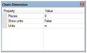
select the units to be used, precision required (Places) and whether to show the units on the dimensions.
- Click a position on screen through which the dimension line, or an imaginary extension of the dimension line, will run (point 1 on the diagram above).
- Click a point on the graphics to start dimensioning from (point 2 on the diagram above). Use snapcodes to make sure you pick exact positions.
- Click a point on the graphics to dimension to (point 3 on the diagram above).
- Keep clicking on further points to dimension to (points 4 to 7 in the diagram above). Each new point is measured relative to the last. If you make a mistake inputting a point, press the Backspace key to remove it.
- Press Enter when you have finished selecting points.
Back to top of page
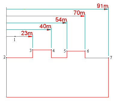
Datum [CAD-Dimension] - Constructs a series of dimensions from a datum point parallel to the X axis.
This command constructs a series of single dimensions, which are automatically spaced by SIS (the dataset scale affects the spacing). Each dimension is measured from a common datum to the point selected.
- Select Datum [CAD-Dimension].
- In the Datum Dimension dialog:
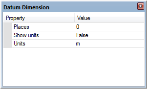
select the units to be used, precision required (Places) and whether to show the units on the dimensions.
- Click a position on screen through which the first dimension line, or an imaginary extension of the dimension line, will run (point 1 on the diagram above). The other dimension lines will automatically be spaced relative to the first one.
- Click a point on the graphics to start dimensioning from (point 2 on the diagram above). Use snapcodes to make sure you pick exact positions.
- Click a point on the graphics to dimension to (point 3 on the diagram above).
- Keep clicking on further points to dimension to (points 4 to 7 in the diagram above). Each new point is measured relative to the first point. If you make a mistake inputting a point, press the Backspace key to remove it.
-
Press Enter when you have finished selecting points.
Back to top of page
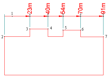
Run [CAD-Dimension] - Constructs a run of accumulative dimensions along a line that is parallel to the X axis.
Like Datum [CAD-Dimension], this command calculates dimensions on a cumulative basis from the first point input. However it displays the dimensions using a different style:
- Select Run [CAD-Dimension].
- In the Run Dimension dialog:
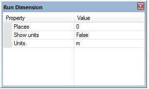
select the units to be used, precision required (Places) and whether to show the units on the dimensions.
- Click a position on screen through which the first dimension line, or an imaginary extension of the dimension line, will run (point 1 on the diagram above).
- Click a point on the graphics to start dimensioning from (point 2 on the diagram above). Use snapcodes to make sure you pick exact positions.
- Click a point on the graphics to dimension to (point 3 on the diagram above).
- Keep clicking on further points to dimension to (points 4 to 7 in the diagram above). Each new point is measured relative to the from point (point 2 on the diagram above). If you make a mistake inputting a point, press the Backspace key to remove it.
- Press Enter when you have finished selecting points.
Top of page
Send comments on this topic.
Click to return to www.cadcorp.com
© Copyright 2000-2017 Computer Aided Development Corporation Limited (Cadcorp).


