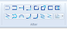
Note: Ensure you are familiar with the meanings of the image status options of editable, hittable, visible and invisible before proceeding with this topic, see Overlays Dialogs.
Selecting Graphics before editing
Using existing item(s) to cut away parts of an existing LineString item
Merging existing LineString items to form one MultiLineString item
Create a MultiLineString item from existing LineString items after deleting any overlap
See Selecting Graphics.
Joins single or multiple LineString items.
Joins two LineString items with an additional LineString item segment.
Shortens or extends LineString item segments without joining them to other LineString items.
Joins two LineString items by extending or trimming them so they meet, joining them into a single polyline.
Allows you to continue a LineString item you constructed earlier, carrying it on to draw further LineString item segments.
The original LineString item and the new LineString item all become part of a single LineString item.
Allows you to redefine a selected path of a LineString item, automatically deleting the old path and connecting the new path into the polyline. It can also be used with topology, see What is Topology.
Deletes a path, a path is any part of a LineString item between two user-selected points. These points may or may not coincide with vertices.
Moves a selected path to a new position. New LineString items are created connecting the path to its original adjacent vertices.
Deletes a segment from a LineString item.
Moves a selected LineString item segment to a new chosen position. The LineString item segment remains joined to its original adjacent vertices by two new LineString item segments.
Replaces curved geometry segments with shorter straight segments.
Creates straight LineString chamfers at the vertices of polylines.
Creates a circular blend at a vertex on a polyline.
Smoothes the geometry of the selected items, keeping segment mid-points fixed. The resulting smooth items will be made up of joined Bezier curves.
Use Smooth Midpoint to have a new curved LineString item created, which touches the original LineString item at the midpoints of its segments.
Smoothes the geometry of the selected items, keeping vertices fixed. The resulting smooth items will be made up of joined Bezier curves.
Use Smooth Vertex to have the new curved LineString item touch the original at its vertices.
Breaks one LineString item into two LineString items.
Slices through Polygon items, cutting them into pieces.
Snips away portions of the selected items inside a Polygon.
Snips away portions of the selected items outside a Polygon.
A LineString item remembers the direction in which it was drawn. The direction is important in the following cases:
If you need to change the direction of an item or item(s), select them first, then use Reverse [Edit-Geometry].
Subtract [Analysis-Boolean] allows you to cut away part of a LineString item using other LineString items to do so. The resultant LineString item is a MultiLineString item. The items used to do the cutting are deleted. See Merging existing LineString items to form one MultiLineString item.
See Clean [Edit-Clean/Simplify].
New MultiLineString items can be created from existing LineString items by merging them in one of several ways, including arcs and circles.
Select the existing LineString items first, then select the appropriate Boolean command from the Alter menu.
Use Union [Analysis-Boolean Operations] to merge the selected LineString items into one MultiLineString item.
If the following two LineString items:
were superimposed as shown below, so that they overlap, you could use Intersect [Analysis-Boolean Operations] to create a new MultiLineString item from the overlapping section:
The new MultiLineString item is the overlap section between the selected LineString items, all parts which do not overlap in the existing LineString items are deleted.
Note: if you want to keep the original, you should make a copy first, then carry out this command on the copy.
Using the same overlapping LineString items as shown for the Intersect command above, you could use Symmetric Difference [Analysis-Boolean Operations] to create a new item of everything except the overlap.
(This command does the opposite of Intersect [Analysis-Boolean Operations].)
See Subtract [Analysis-Boolean Operations]
The Align commands can be used to square LineString items which should be, but are not quite, either:
This facility is particularly useful for tidying digitised data.
All LineString items which diverge by 14 degrees or less are rotated so that they form right-angles. Any LineString items which diverge by more than this are left untouched. The LineString items are rotated about their midpoint in order to align them.

You can set the axes to any angle before aligning your LineString items to them. See Rotate [CAD-Axes].
The dimension graphics consist of:
A set of dimensions can be picked up and copied/moved/deleted as a single item. To pick up the dimension set, click anywhere on the leader lines, or click on the dimension line anywhere except on its vertex.
The lines are drawn using the pen indicated in the styles toolbar, and this can be changed in the normal way.
For all dimension types except distance, the dimension line can be moved closer to or further from the items you have dimensioned. Do this by clicking and dragging on its vertex.
The leader lines are automatically stretched or shortened accordingly.
The leader lines may be stretched or shortened individually. When selected they have a handle which is offset from the end of the line. Click and drag this handle to stretch the leader line.
The leader lines may be moved by their handle so that they dimension to a different position. Dimensions are dynamic; if you move a leader line in this way, the dimension value is automatically updated:
The dimension text is a point text item. You can edit any of the point text properties in the usual way. See Creating Text - Simple Text.
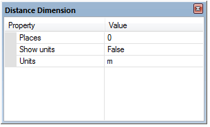
In the Distance Dimension dialog, use the Show units drop-down box False/True settings to determine if units are displayed.

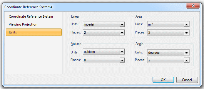
Use the Places property to change the precision, and the Units property to change the units used. The units are the linear units selected on the Units tab of the Coordinates Reference Systems dialog:

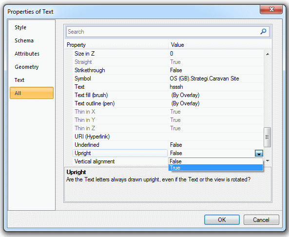
If your text is upside down, set Upright to True in the Properties of Text dialog:

SIS uses a symbol called DimArrow as a dimension marker. You can change this to any symbol stored in the enabled libraries by changing the symbol property.
Send comments on this topic.
Click to return to www.cadcorp.com
© Copyright 2000-2017 Computer Aided Development Corporation Limited (Cadcorp).