Microsoft SQL Server Microsoft SQL Server
Location: Overlay Types dialog > Databases > Cadcorp View Points > Microsoft SQL Server
The Microsoft SQL Server Connection dialog will be displayed:
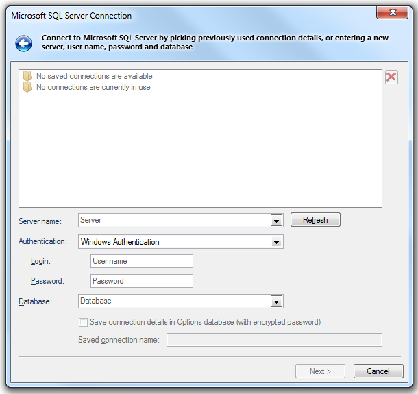
Server name
Select a server name from the drop-down list, or type the location of the server where the database you want to access is located. Selecting the database on the server is a separate action. Click Refresh to refresh the list. If the server instance uses a port other than the default specify the port after the server address, in the form: Server\SQL2016, 1434
Authentication
Windows Authentication
Select if the provider is to request a secure (or trusted) connection to a Microsoft SQL Server running in Windows NT. When selected, SQL Server uses integrated login security to establish connection using this data source, regardless of the current login security mode at the server. Any login ID or password supplied is ignored. The SQL Server system administrator must have associated your Microsoft Windows network ID with a SQL Server login ID.
SQL Server Authentication
Select to use a supplied user name and password to authenticate your logon information to the data source.
Login
Type the user ID to use for authentication when you log on to the data source.
Password
Type the password to use for authentication when you log on to the data source.
Database
Type the name of the database that you want to access or select it from the drop-down box.
Save connection details in Options database (with encrypted password)
Check this tickbox if SIS should store these connection details in the Options database. The password will be stored in encrypted form for security.
Saved connection name
This text box will become active if the Save connection details in Options database (with encrypted password) tickbox is checked. Enter a meaningful name for this connection. This text box cannot be left blank and the same name cannot be used twice.
If the Microsoft SQL Server Connection has been made previously, and the connection details saved, the Microsoft SQL Server Connection dialog will be displayed in the form shown below:
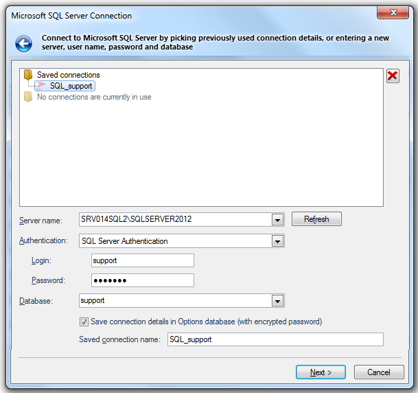
In this case click on one of the Saved connections or Currently used connections (if any are in use) to complete the connection details.
Click Next.
The Recordset dialog will be displayed:
Database Tables/Columns
Displays the tables and columns available in the connected database. Highlight the required table or column in this pane. Database names are case sensitive, use upper-case names for interoperability.
Add/Remove
Click the Add button to add the selected column to the chosen list. If a table is selected then all its columns will be added.
The Remove button removes a selected column from the Selected columns list.
Selected columns
Displays the selected database table columns. Move the horizontal slider to the right to reveal the Alias column, this column is used to map the database column name onto a SIS property/attribute name. If the recordset is being used as part of a database-based dataset, then you can enter existing property names (e.g. _shape$) to redefine the created items' properties.
If you wish to assign a column to be used for hyperlinks, then when you have clicked Add, scroll the pane horizontally to show the Alias column. In the column that is to contain the hyperlink data rename the Alias to _URI$:
When the dataset is displayed in the Map Window the Properties Control Bar will display any property value that it recognises as a URL, or as a file or folder name, as a clickable link.
SQL Where
Enter the SQL syntax clause that can be used to join several different tables, or restrict which rows are imported. Do not use the WHERE SQL keyword.
Click Next.
The View Points dialog will be displayed:
.png)
Point Configuration
X Field
This drop-down box allows you to select the column to use for X values.
Y Field
This drop-down box allows you to select the column to use for Y values.
XY Units
Linear - X/Y values use Linear units. This will usually be the case in Orthoganol coordinate reference systems, for example OS National Grid.
Angular - X/Y values use Angular units. This will usually be the case in Latitude/Longitude coordinate reference systems.
The final drop-down box allows you to select the units for X/Y values, these can be; the Coordinate reference system used, degrees, radians, DMS, gradians or DM.
Note: The value in the drop-down tells SIS the format to expect from the datasource. SIS will then convert and display the points in degrees. When selecting DMS be aware that SIS uses a coma as a separator within its coordinates i.e. x,y,z. If your datasource format is DD,MM,SS.S only the DD part will be used, therefore you need to replace the coma with another character such as double-quotes (any character except a coma) to get DMS.
Create 'Empty' Items for unusable coordinates
Check this tickbox if you want an Empty Item to be created if one or more of the coordinates could not be parsed correctly.
Optional Configuration
ID Field
If one of the SQL columns contains unique positive integer values, you can use that column for the _id& property. This can help when writing GISLink customisations or SIS control applications to coordinate SIS items and other database data.
Z Field
The column to use for Z values, or height above sea-level. If you leave this field empty, then 2D points will be created.
Z Units (linear)
The units of the Z coordinates in the database.
Overlay Configuration
Name
This displays the overlay name which may be changed if required.
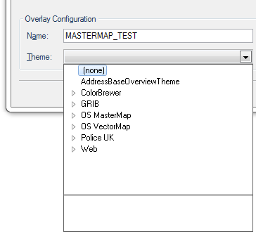
Theme
This drop-down shows any Themes associated with the overlay:
If you do not want to modify the dataset's Coordinate Reference System, Scale, etc. click Finish.
If you do want to make some changes click the More Properties... button.
If you click the More Properties... button the small View Points dialog will be displayed:
Coordinates:
Displays the coordinate reference system that the dataset items are defined in. To view or edit the coordinate system details drop-down the combo-box list, and press the right arrow at the bottom to display the Coordinate Reference System dialog.
Feature Table:
This is the feature table to use for feature-coded items in this dataset. Feature-coded items get information about their feature code either from this feature table, or, if set, their own Feature Table property.
Scale:
The default viewing scale for this dataset. This will affect how Text items convert their point heights into world sizes.
Properties... button
Click the Properties... button to display the resizable Cadcorp View Points dialog showing the values of properties which may be viewed or edited:
.png)
Click Close to return to the small View Points dialog, click OK to return to the initial View Points dialog and click Finish.
Send comments on this topic.
Click to return to www.cadcorp.com
© Copyright 2000-2017 Computer Aided Development Corporation Limited (Cadcorp).
.gif)