 Topology Topology
Location: Theme Types dialog > Annotation tab > Topology
Availability: Map Modeller, Map Editor.
The Topology theme shows topological structure.
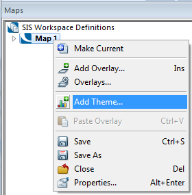
Click Add Theme [Home-Map] or highlight the SIS Workspace Definition (SWD) in the Maps Control Bar and select Add Theme...
If the SWD contains more than one overlay the following Theme Overlay dialog will be displayed:
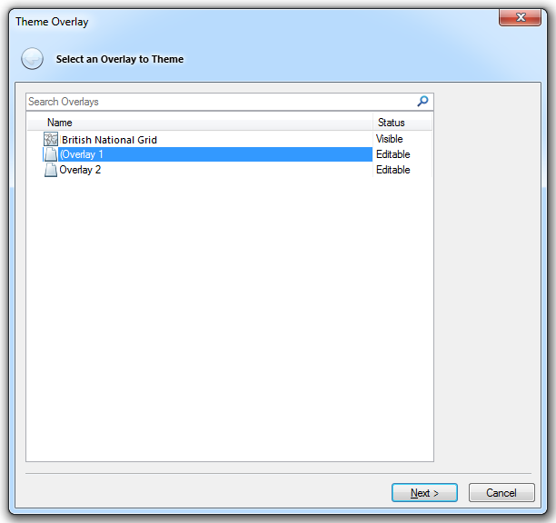
Either double-click the overlay to be themed or select it and click Next.
The Theme Types dialog will now be displayed:
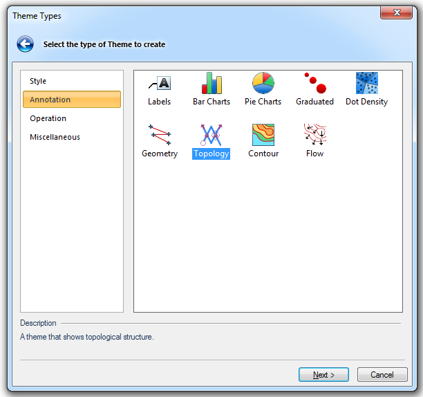
Go to the Annotation tab and either double click the Topology icon or select it and click Next.
The Topology Styles dialog will now be displayed:
The Topology theme allows you to use symbols to represent the properties of nodes and the flow characteristics of links. For details of assigning flow characteristics to links and turning rules at nodes (junctions) see below:
In the Topology Styles dialog choose the required parameters:
Node annotation symbols
Choose Symbols to indicate automatic nodes (most nodes are automatic) and non-automatic nodes.
A single node is one which is at the end of a dangling segment (it only has one link entering it). A junction is where a node has had turning rules assigned. Edge nodes often occur at the edge of a map tile. They are not the natural end of a link, so SIS searches the adjacent map tile for continuity. You can see whether a node is an edge node by checking its Edge property (_bEdge&).
The following diagram shows single, junction and non-automatic nodes:
Sometimes a node will have more than one symbol. For instance, a node which has turning rules assigned and has the Automatic property can display both the Junction and Automatic symbols.
Automatic
Choose the annotation symbol for automatic Node items.
Non-auto
Choose the annotation Symbol for non-automatic Node items.
Edge
Choose the annotation Symbol for Edge Node items.
Junction
Choose the annotation Symbol for Node items with turning rules.
Single
Choose the annotation Symbol for Node items with only one connected Link item.
Link annotation Symbols
For details of flow directions, direction flags and how to determine the turning rules at junctions, see Topology.
A link is shown as blocked if no flow is allowed through it (a value of 3 for the Direction flags property).
If the link only allows flow in one direction (a value of 1 or 2 for the Direction flags property), it uses the direction symbol.
If flow in both directions is allowed (Direction flags value 0), no symbol is shown.
Direction
Choose the annotation symbol for one-way Link items.
Blocked
Choose the annotation symbol for blocked Link items.
Fixed size symbols
With this option selected, the symbols remain the same pixel size on screen while you zoom in and out (subject to the scale thresholds). Otherwise they act like the rest of the graphics, i.e. they become smaller as you zoom out and larger as you zoom in.

Click here for a description of the functions of these three buttons.
Click here for Topology Theme properties.
Send comments on this topic.
Click to return to www.cadcorp.com
© Copyright 2000-2017 Computer Aided Development Corporation Limited (Cadcorp).