Creating contour lines on a TIN

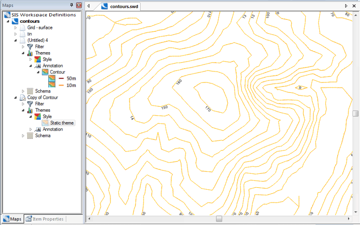
Select Add Theme [Home-Map], select the overlay containing the TIN, select the Contour theme, from the Annotation tab, and click Next.

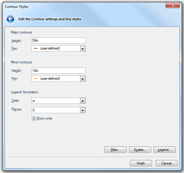
In the Contour Styles dialog you can choose the spacing for the Major contours and Minor contours, and the Pens to use for them.


Major contours

Height

Draws major contour lines at each elevation that is a multiple of this height.

Pen

Pen to use for major contour lines.

Minor contours

Height

Draws minor contour lines at each elevation that is a multiple of this height, unless the elevation is also a major contour.

Pen

Pen to use for minor contour lines.

Legend Annotation

Units

Units to use in theme legend. (SIS does not automatically place labels on the contour lines.)

Places

Decimal places to show in theme legend.

Show units

Check this tickbox if the units are to be shown in the theme legend.

Filter, Scale and Legend buttons

Click here for a description of the functions of these three buttons.

Creating smoother contour lines

If you require smoother contour lines, use one of the following methods, use Method 1 if there are not too many contours:
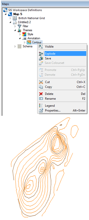
  1. Use the Explode command to generate joined-up contour lines, these are MultiLineString items, designated as a Static theme. You can use the Labels theme to label these contours, if required.


    Select the newly created MultiLineString items and use Smooth Vertex [CAD-Alter]. This makes very smooth contours, but they may cross over each other, and may not be very accurate.

  2. Before creating the contours, subdivide the TIN item, perhaps more than once, using the TIN item command Subdivide [Edit-TINS], see Smoothing TINs.

Example of creating smoother contour lines using Method 1

This example illustrates Method 1 described above, and makes use of the Label settings for linear items controls in the Label Styles dialog.

  1. Explode the contour theme.


  2. Add a Label theme.

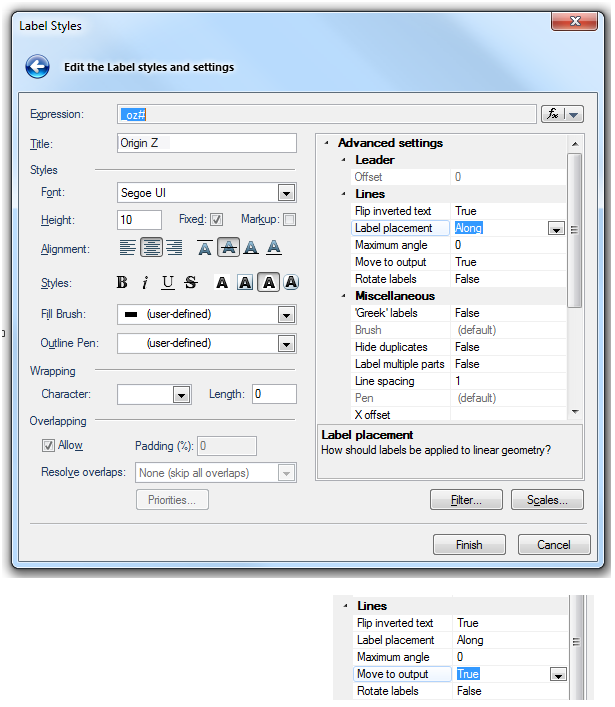
    In the Label Styles dialog go to the Advanced settings pane and choose Along from the Line placement drop-down box and set the Move to output drop-down box to True:


  3. The result of exploding the theme are MultiLineStrings with originZ values, one MultiLineString for each contour value. Therefore there will now be very few labels shown on the screen.

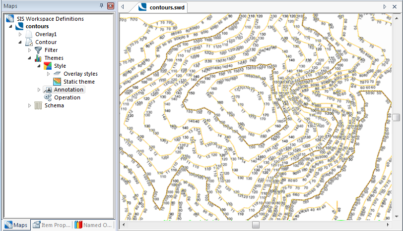
  4. Select Decompose [Create-Edit]. Each contour line is now broken up into its component lines which were created from a TIN, this results in masses of LineString segments and masses of labels:

  5. With the results still selected select Join LineStrings [CAD-Alter].

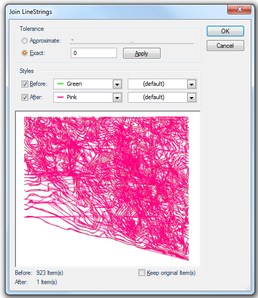
    In the Join LineStrings dialog select the Exact radio button and enter 0 (zero)


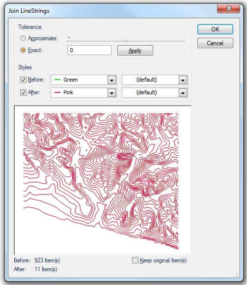
    click Apply if you wish to see the effect in the preview pane:


    Click OK.

  6. The result will be as shown:

Method 2 is theoretically more valid, and usually makes more accurate contours which will not cross. However, the resulting contours may not be as smooth as Method 1.

The following diagram shows a TIN with contours applied, then the same TIN subdivided twice before having contours applied:


Top of page

Send comments on this topic.

Click to return to www.cadcorp.com

© Copyright 2000-2017 Computer Aided Development Corporation Limited (Cadcorp).