{"Pen":{"Colour":{"RGBA":[0,0,0,0]}}}
The resulting line would be:

Pens are used to draw and control the appearance of LineString items, and the colour of Text items.
Every Item in SIS is displayed with a Pen.
A Pen has:
A Pen can also:
Pen (and brush) definitions are stored in Named Object Libraries. SIS comes supplied with a variety of Pens (and brushes), and you can also create your own. see Creating, Choosing and Editing Pens.
A Pen may be specifically assigned to individual items, or may be assigned to an overlay so that all items on that overlay use the same Pen by default.
In SIS Pens (and Brushes) are specified in JSON (JavaScript Object Notation). Examples of the use of JSON for Pens are given in the user-defined Pens topic.
As a brief introduction to the use of JSON:

Whenever LineString and Text items are about to be drawn, SIS looks for a Pen object in the following order:
Once a Pen name has been decided on, one of two things will happen. If the Pen name is user-defined then a Pen will be created from the user-defined name. Otherwise the Named Object Libraries are searched through for a Pen object of that name. If a Pen is found then it is used to draw the LineString or Text item.
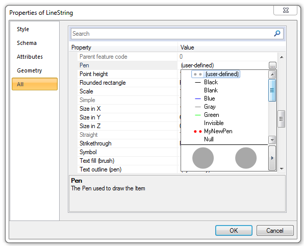
A Pen can be selected from the Pen drop-down box in the All tab of the Properties of ... dialog:
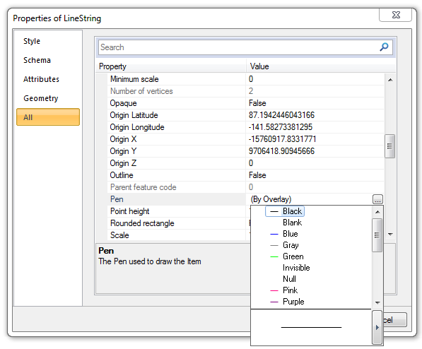
Initially the Pen will be set to (By Overlay). This means the Pen will use the characteristics as specified for the Overlay.
To change the Pen settings click in the Pen row of the above dialog, a three dot button will then be shown to the right of the Pen value:
Click this button to display a drop-down list as shown above.
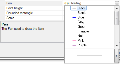
The Pen may be changed to any available Pen (any Pen in any of the enabled libraries) by selecting it from the list and double-clicking on it.
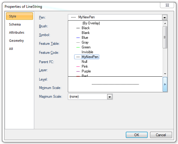
For example if a Pen called MyNewPen has been created in the (temporary) library:
Then MyNewPen will be included in the drop-down list (using the styles as defined in the (temporary) library).
The style of LineString item that would be produced by the highlighted Pen is shown in the preview box at the bottom of the drop-down list. In this example MyNewPen is a black dashed line:
This will display the Edit Pen - MyNewPen dialog where the Pen settings may be changed, this can be done for any of the Pens in the drop-down list and is fully explained in Creating, Choosing and Editing Pens. Any changes made to a Pen will result in the Pen showing as (user-defined) in the drop down list. This means the Pen does not have a definitive name and is defined by JSON.
Note: From SIS 7.0 onwards Pens (and Brushes) are specified in JSON. JSON for Brushes is fully explained in Creating, Choosing and Editing Brushes.
Changing MyNewPen from a black solid line to a dash/dotted line of different thickness or degree of transparency will result in MyNewPen becoming (user-defined), the drop-down list will now appear as follows:
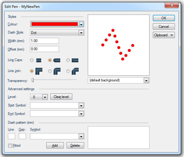
If MyNewPen is edited in the (temporary) library to give it a colour red, a line style of dot, a width of 1.00mm, with end caps as round the drop-down box and preview may look like:
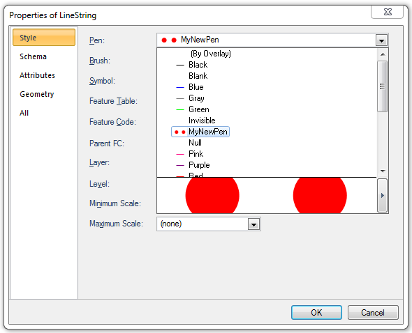
To change a Pen style click on the right pointing arrow at the right-hand side of the preview box in the Properties of LineString dialog Style tab. This will cause the Edit Pen - xxxx dialog to be displayed where the Pen settings may be changed:
This can be done for any of the Pens in the drop-down list and is fully explained in Creating, Choosing and Editing Pens. Any changes made to a Pen will result in the Pen being shown as (user-defined) in the drop down list. This means the Pen does not have a definitive name and is defined by JSON, see below for details of JSON.
The thirteen named Pens in the Standard library; Black, Blank, Blue, Grey, etc. exist as named objects and may be considered to be SystemPens.
System Pens are defined by JSON as follows:
{"Pen":{"Colour":{"RGBA":[0,0,0,0]}}} for the Black Pen
{"Pen":{"Style":"Null","Colour":{"RGBA":[0,0,0,0]}}} for the Blank Pen
{"Pen":{"Colour":{"RGBA":[0,0,255,0]}}} for the Blue Pen
{"Pen":{"Colour":{"RGBA":[128,128,128,0]}}} for the Grey Pen
.
.
etc.
.
.
{"Pen":{"Colour":{"RGBA":[255,255,255,0]}}} for the White Pen
{"Pen":{"Colour":{"RGBA":[255,255,0,0]}}} for the Yellow Pen
The components of this code define the fact that the object is a Pen, the RGB values give it its RGB colour specification, the fourth parameter 'A' is a measure of transparency in the range 0 (zero) to 255, by default this value is 0 which defines the object as fully opaque, 255 defines fully transparent.
A User-defined Pen is any Pen which has a custom coding or has had any changes made from the standard system Pen code, this could involve anything from a minor colour shade change through to the creation of a Pen with a number of levels (Multi-level Pen).
User-defined Pens do not exist as named objects. They are displayed according to their defining JSON. This code can be copied from the Edit Pen dialog > Clipboard > Copy as JSON option:
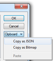
The code can be pasted into any text editor where it can be examined and edited if required and pasted back into the Edit Pen dialog using the Clipboard > Paste option.
In its simplest form a user-defined Pen may have the JSON:
{"Pen":{"Style":"Dash","Colour":{"RGBA":[0,0,255,0]}}}
in this case the parameter "Dash" has been added to the code so that the Pen will produce a dashed blue LineString instead of a solid one.
See the User-defined Pens topic for full details.
A Multi-level Pen is a Pen object defined on more than one level (any levels between 0 and 31), each level having a different style, thickness, etc.
A typical use of a multi-level Pen could be to depict a major road, as drawn in a road atlas. The convention for this is to depict it as a thick red line bordered in black. This may be thought of as a very thick black line, with a thinner red line running along the centre. To create it, level 0 is given a width of 2 mm, coloured black with level 1 set to 1mm and coloured red. This would display as a 1mm red line, bordered by a 0.5mm black line on each side.
Because the wide black line is drawn first (level 0), followed by the thinner red line (level 1), junctions will automatically display correctly.
See Multi-level Pens for an example of creating a multi-level pen.
Send comments on this topic.
Click to return to www.cadcorp.com
© Copyright 2000-2017 Computer Aided Development Corporation Limited (Cadcorp).