Creating contour lines on a TIN
Contour lines represent constant elevation and show the topography of the landscape. More information on Contour Lines 
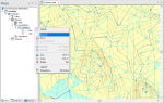
- Select Home > Map > Add Theme.
- Select the overlay containing the TIN,.
- Select Annotation > Contour theme and click Next.
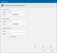
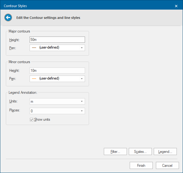
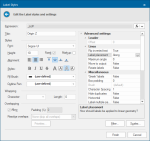
- In the Contour Styles dialog you can choose the spacing for the Major contours and Minor contours and the Pens to use for them.
| Option | Description | |
|
Major contours Height |
Draws major contour lines at each elevation that is a multiple of this height. |
|
|
Pen |
Pen to use for major contour lines. |
|
|
Minor contours Height |
Draws minor contour lines at each elevation that is a multiple of this height, unless the elevation is also a major contour. |
|
|
Pen |
Pen to use for minor contour lines. |
|
|
Legend Annotation Units |
Units to use in theme legend. (SIS Desktop 9 does not automatically place labels on the contour lines.) |
|
|
Places |
Decimal places to show in theme legend. |
|
|
Show units |
Check this tickbox if the units are to be shown in the theme legend. |
|
Filter, Scale and Legend buttons
TIP: Click here for a description of these functions.
Creating smoother contour lines (Method 1)
There are two ways to create smoother contour lines; use Method 1 if there are not too many contours:
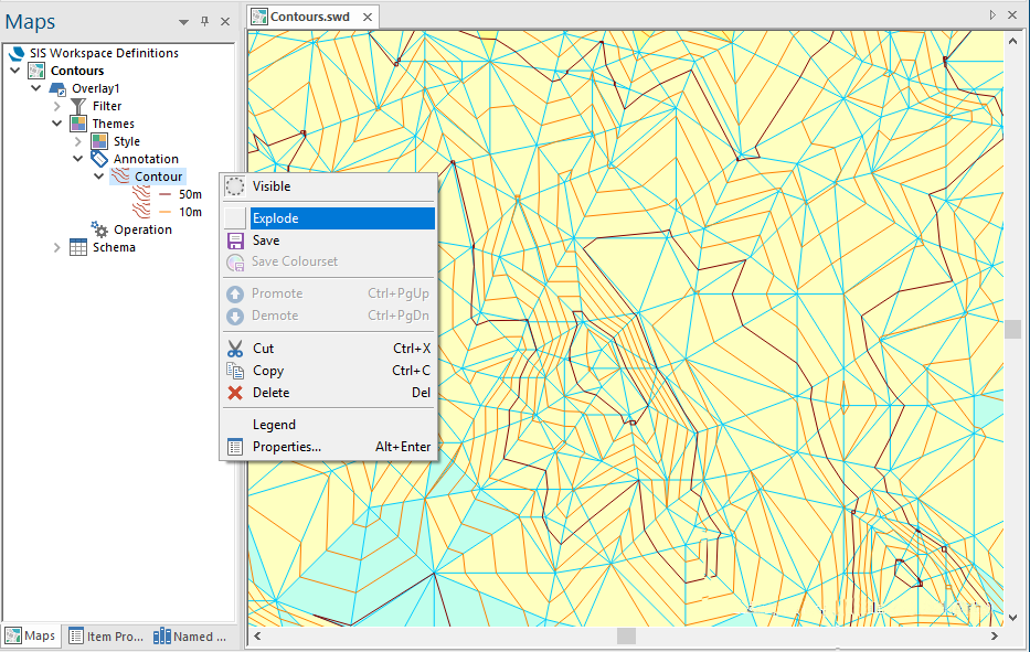
- Use the Explode command to generate joined-up contour lines.
- These are MultiLineString items, designated as a Static theme. You can use the Labels theme to label these contours if required.

- Select the newly created MultiLineString items and use CAD > Alter > Smooth Vertex. This results in very smooth contours. But beware the contour lines may cross over each other and are not very accurate.
-
Before creating the contours, subdivide the TIN item (ideally more than once) using the TIN item command Subdivide (Edit > TINS).
 Related Topics

Example
This example illustrates Method 1 and uses Label settings for linear items controls in the Label Styles dialog.
- Explode the contour theme.
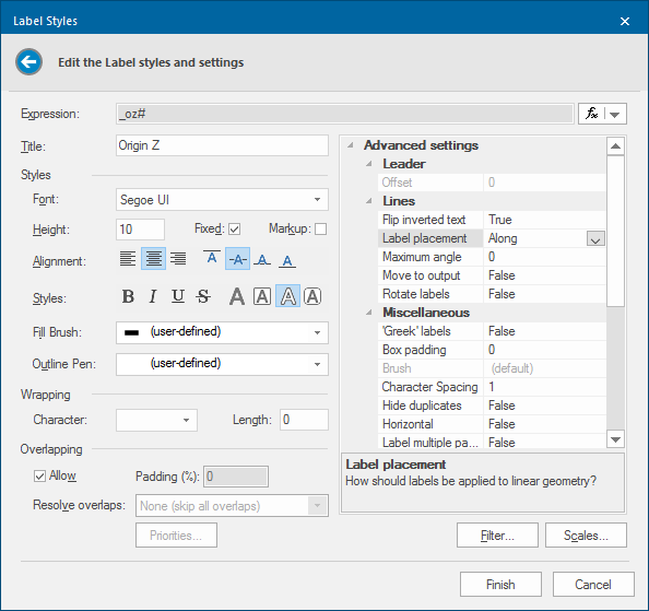
- Add a Label theme.
- In the Label Styles, navigate to Label Placement inside the Advanced settings pane.
- Choose Along from the drop-down box and set the Move to output drop-down box to True.
- The result of exploding the theme are MultiLineStrings with originZ values, one MultiLineString for each contour value. Therefore there will now be very few labels shown on the screen.
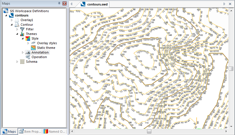
- Select Decompose.
- Each contour line is now broken up into its component lines which were created from a TIN, this results in masses of LineString segments and masses of labels:

- With the results still selected, choose CAD > Alter > Join LineStrings
- Select the Exact radio button and enter 0 (zero).
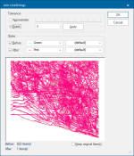
- Click Apply if you wish to see the effect in the preview pane:
- Click OK.
- The result will be as shown:

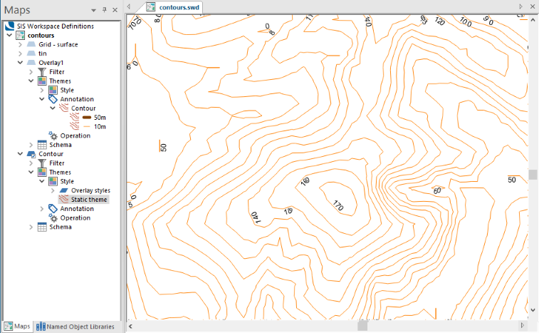
Method 2
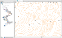
Method 2 is theoretically more valid and usually makes more accurate contours which will not cross. However the resulting contours may not be as smooth as Method 1.
The following diagram shows a TIN with contours applied, then the same TIN subdivided twice before having contours applied.