Creating Symbols
A symbol can be a combination of LineString items, Polygon items, box text and bitmaps. A symbol however cannot include point text and topological structures; although you can use these items they will not be displayed.
- Open a new, empty SWD.
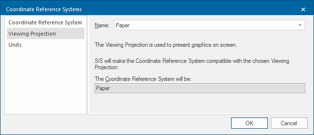
- Select CRS Viewing Projection tab and change the Viewing Projection to Paper

- Create the graphics that make up the symbol. You could use the Create >Simple and Create > Advanced commands, i.e. LineString, Polygon, Rectangle, etc. to create the symbol or you could use a bitmap. If using a bitmap for a logo, consider resizing the bitmap using the Move Scale entry so that it is the correct size.
- Use the Measure functions to obtain the correct size. If you are using a bitmap for a symbol, use Insert From File (Create > Miscellaneous) to import the bitmap.
- Select all the graphics which make up the symbol.
-
Select Create > Miscellaneous > Symbol.
-
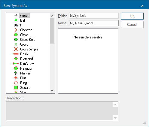
Click a position for the centre of the symbol. The centre is the position by which you will later place the symbol. The Save Symbol As dialog will be displayed:
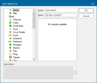
- In the Save Symbol As dialog, enter a Folder name if you want to create a new folder (you will need to do this if there are no other symbols in the enabled libraries) or select an existing folder name if appropriate. All symbol folders in all enabled libraries are listed.
-
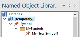
Enter a Name for the symbol. Symbols are named objects, see Named Objects, the symbol is then stored in the current library:
- You can delete the graphics used to form the symbol as these are no longer required.
Creating complex Symbols
Symbols can be extremely complex objects, making extensive use of the advanced capabilities of Cadcorp SIS Desktop such as scale thresholds and levels.
For example it is possible to create symbols which appear differently at different scale thresholds.
Ordnance Survey Symbols (UK specific)
Ordnance Survey files contain locations for symbols of ordnance benchmarks, pylons, flow arrows, etc. These Ordnance Survey symbols are stored with appropriate names (e.g. Bench Mark, Pylon, Flow Arrow) in the OS DNF, OS NTF and OSNI NTF folders in the (standard) library.
Creating a symbol from an image
Note: Make sure that the Brush is set to Blank to make transparency work.
-
Set the Map Window Coordinate Reference System to Paper.
- Select Insert from File
- When you bring an image into a map window, it is resized to fit the current viewed area. An easy way to create the symbol at the appropriate size is to zoom in first, then use Insert from File.
- To zoom in to the correct scale: Create a square with the dimensions of the size you require the symbol to be – i.e. with equal x and y of 0.01m (10mm). Zoom extents and delete it or drop an existing symbol of the right size down i.e. circle, right click explode, zoom extents. This zooms in to the appropriate scale.
-
Right click select Properties or use the Format tab to set the Pen and Brush to be Blank. This will enable the transparency function if used and remove the outline.
- Create the Symbol and save in a NOL.
Note: Some image formats support transparency, i.e. GIF, PNG, TIFF, either through a transparent color or an alpha channel. Transparency can be set in a graphics package before inserting the image in to Cadcorp SIS Desktop.