Dimensions
Dimensions are constructed on the current overlay (or on the first editable overlay if there is no current overlay).
Dimensioning commands offer four ways of dimensioning graphics automatically. You can dimension any graphics as long as they have a status of hittable or editable. ![]() Related Topics
Related Topics
The dimension graphics consist of:
- Line items (the dimension and leader lines)
- Text items (the dimension text)
- Point items (the dimension arrow). The dimension text is displayed in the current default font and in the colour of the pen used for the dimension line.
Constructing Dimensions
Here is an example on how to construct a simple linear dimension between two points.
We will use the Distance (CAD > Dimension) command to create a single dimension between two points. The dimension line takes no account of the current X axis but is drawn directly between the two points chosen.
- Select CAD > Dimension > Distance.
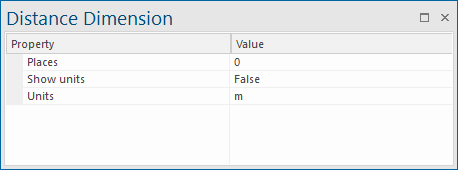
- In the Distance Dimension dialog:
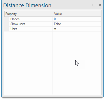
select the units to be used the precision required (Places) and whether to show the units on the dimensions. - Click the two points between which you want to dimension. If you make a mistake when entering a point, press the Backspace key to remove it.
Cadcorp SIS Desktop offers you more options to work with Dimensions. See list below:
| Option | Description | |
| Chain Dimension | Constructs a chain dimension along a line that is parallel to the X axis. | |
| Datum | Constructs a series of dimensions from a datum point parallel to the X axis. | |
| Run | Constructs a run of accumulative dimensions along a line that is parallel to the X axis. | |
Selecting and moving/copying the dimension set
A set of dimensions can be picked up and copied/moved/deleted as a single item. To pick up the dimension set, click anywhere on the leader lines, or click on the dimension line anywhere except on its vertex.
Editing the LineString items
Once created, dimensions can be edited by selecting the dimension item and changing its properties in the local Properties command.
- For all dimension types (except distance) the dimension line can be moved closer to or further from the items you have dimensioned. Do this by clicking and dragging on its vertex.
- Again with the exception of Distance dimension lines are created parallel to the X axis. If you want dimension lines at a different angle, ensure you rotate the axes first.
- The leader lines are automatically stretched or shortened accordingly.
- The leader lines may be stretched or shortened individually. When selected they have a handle which is offset from the end of the line.
- Click and drag this handle to stretch the leader line.
- The leader lines may be moved by their handle so that they dimension to a different position. Dimensions are dynamic; if you move a leader line in this way, the dimension value is automatically updated:
Editing the Text
The dimension text is a point text item. You can edit any of the point text properties in the usual way. See Creating Text > Simple Text.
In the Distance Dimension dialog, use the Show units drop-down box False/True settings to determine if units are displayed.
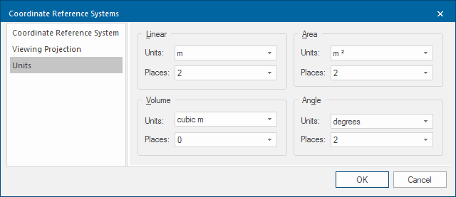
Use the Places property to change the precision and the Units property to change the units used. The units are the linear units selected on the Units tab of the Coordinates Reference Systems dialog:
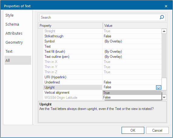
If your text is upside down or at an angle, set Upright to True in the Properties of Text dialog:
Using a different Symbol
SIS Desktop 9 uses a symbol called DimArrow as a dimension marker. You can change this to any symbol stored in the enabled libraries by changing the symbol property.