Polygon
A Polygon item is a distinct class of item with its own set of properties. Polygons have one or more closed 'loops'.
- Simple Polygons
- MultiPolygons
- Photos
- TopoPolygons
- QZones
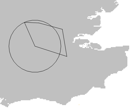
- Buffer zones
To create a Polygon:
-
Select Create > Simple > Polygon.

- Begin drawing your polygon freehand in the map window.
-
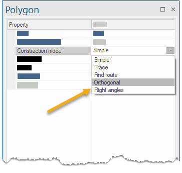
The Polygon options window is displayed automatically when you choose the Polygon option. Simply edit the options to instantaneously customise your polygon.
.png)
This dialog remains open allowing you to edit Polygon parameters even during usage.
This display field is an information field showing the dynamic area of the polygon item being drawn.

Construction mode determines how snapped or typed positions are interpreted (including the offset from those positions from which to create the Polygon).
a. Simple:
Enter the start position of the Polygon item by snapping to a position on the screen or typing a coordinate. The corner of the Polygon item will now be locked to that point and can be sized by dragging and snapping to positions on the screen or typing coordinates.
Press Enter or double-click when you have finished the Polygon.
Press Backspace to remove a point. Each subsequent press of the Backspace key will backtrack through the previous points.
b. Trace
This mode constructs a Polygon by tracing over existing graphics.
Tracing over base data is simple and reliable in Cadcorp SIS Desktop 9.1 when used in conjunction with pan and zoom and ability to display more than one view of the map.
Snap or type a position for the start of the trace (ideally choose a vertex on the geometry to be traced) and snap a position to trace to.
To search for a continuous path between the first and second point, click over existing geometry. The trace will follow exactly over the path of the geometry being traced, irrespective of how many intermediate vertices it contains.
- The trace sequence is drawn on screen using a thick outline. Press Backspace to return to the previous trace point, or Shift+Backspace to step back over the vertices of the last intermediate trace sequence.
- The trace path will not jump between different bits of geometry. To do this, navigate to the intersection between two pieces of geometry.
- To trace over an existing geometry completely, click the first point. Now hold the CTRL key down and click anywhere along the geometry to be traced close to the first point in the direction you wish to trace. SIS Desktop will not insert a vertex at this point but will attempt to trace the geometry right to its end (no matter how long or how many intermediate vertices are needed).
- You can also enter a position while holding the Shift key and jump directly to the position you create; this NEED NOT be on existing geometry.
- If the start and end positions of a trace segment are on topological Link items, SIS will automatically perform a topological route-find using a shortest-route algorithm.
- Press the Enter key to accept the trace sequence or press Ctrl+Enter to close the shape, joining the last point back to the first. A LineString item will be created along the traced path.
c. Find route
SIS Desktop will look for a route between entered positions. The route can be made up of geometry from any item. If your positions are far apart, Cadcorp SIS Desktop 9.1 may spend some time looking for a route.
d. Orthogonal
All Polygon item segments are corrected to be parallel to the X and Y-axes, giving right-angled corners.
For Polygon items at angles other than 0, 90, 180 and 270 degrees, change the orientation of the axes Rotate (View > Axes).
e. Right angles
Each Polygon item segment will be created at right-angles to the previous segment.
Before the final Polygon item is created, Cadcorp SIS Desktop 9.1 can offset it from your entered positions. Entering an offset will result in the new Polygon item set apart by a specified distance, (positive values result in an offset to the left of the entered position and negative values to the right of the entered positions).
To draw several Polygon items at once which trace existing graphics, you can enter several space separated offset values, for example:
100m 200m 500m 2000m
or use REP, R or r for repeated offsets, for example:
100m REP 4 - this would give 4 offsets spaced at 100m
This is an information field showing the dynamic perimeter of the polygon item being drawn, reported as an integer in the current units.
You can enter a value here to override the height of each snap with a fixed value.
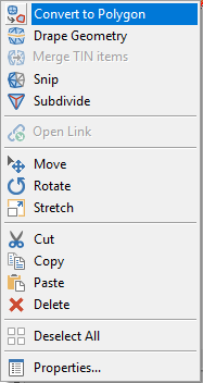
Closed LineString items created with LineString and Freehand are not Polygon items. However any LineString item (closed or not) can be converted into a simple Polygon item using the Convert to Polygon local command.

Use this option to construct Polygon items for defining enclosed areas. The Polygon can be used with tracing, route-finding and orthogonal graphics.
