Geo-referencing files
Some data products (GIS, Digital Mapping and Remote Sensing software) provide data files that are geo-referenced. These can be included as overlays in the normal way, using Overlay [Home-Map]. If the graphics in the data file have been positioned using a coordinate reference system, the data appears in the correct geographical position.
Other data files, mostly created in CAD, or scanned images which have no regard to their location in the world, may have selected a convenient local position as the origin of the coordinate reference system for the data. In this case, SIS provides the ability to move the data to its correct geographical position, rotating it as necessary, and defining the units of measurement used. You can relocate it by selecting any item from the overlay, then using Move Dataset [Edit-Geometry-Arrange-Dataset], described below.
To display a file which is not correctly geo-referenced, it is important that you know the geographical location of at least one point on the graphics.
For example, if you were using the National Grid coordinate reference system, you must establish the National Grid reference of a point on the graphics. (You may need to consult the provider of the data file to obtain this information.)
The following example uses an Ordnance Survey MasterMap DXF file which is to be positioned within the National Grid.
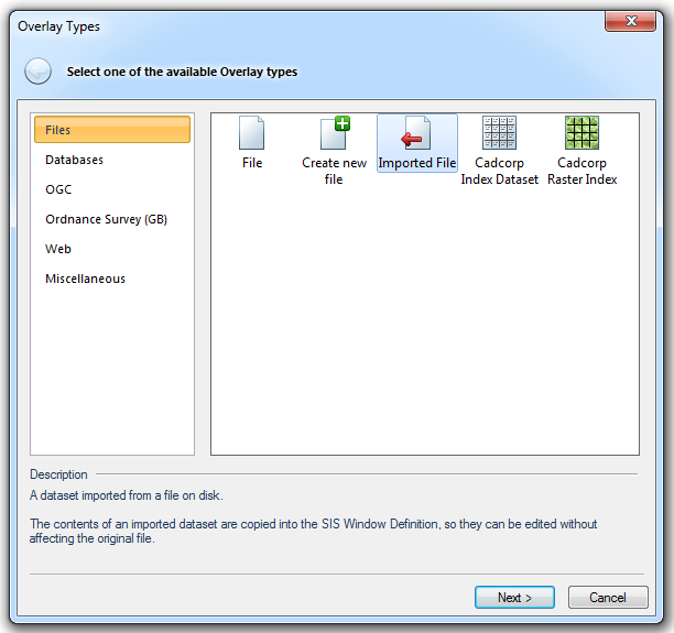
- Select the Imported File option in the Overlay Types dialog to add the DXF file to the SWD. It is a good idea to remove any other overlays (select them, then click the Delete button), or make them invisible (click on the overlay icon(s) in the Maps Control Bar).
- Do not be surprised if you cannot see any graphics. Remember, the DXF file is not geo-referenced, so the origin of its coordinate system (0, 0) has been placed at the origin of the current map coordinate reference system. In the case of the National Grid, this is near the Isles of Scilly which lie off the south west coast of Britain.
- Choose the Zoom Overlay command from the DXF overlay’s local menu.
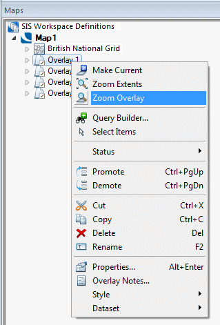
This will shift your current view to display the full extent of the chosen overlay (the DXF file).
Select any item in the DXF dataset by clicking on it.
-
Choose Move [Edit-Geometry].
-
For the position to move from, click on a point on the DXF graphics whose coordinate position you know.
-
If you want to scale or rotate the dataset before placing it, press Enter to see the Transformation dialog:
The Transformation dialog enables you to increase the size of the file by scaling it; mirroring it, or rotating it around one of its axes.
Scale: - Enlarge or reduce the items on the cursor by the specified value. This value is relative to its current size, and ignores any previous enlargement or reduction.
Mirror - Create a mirror image of the graphics on the cursor, using the specified angle as the mirror plane. 0 degrees is horizontal, 45 degrees is bottom-left to top-right, and 90 degrees is vertical.
Rotate about Axes
X:/Y: - Define three-dimensional rotation about the X/Y axes. These options are only useful in 3D modelling.
Z: - Rotate the items on the cursor through the specified angle. Positive angles are anti-clockwise, negative angles are clockwise.
On completion click OK.
-
To place the selected point in its correct geographical location, type in its coordinates (in the Position bar at the bottom of the SIS Workspace), or click on existing graphics which are at the correct location.
-
When the DXF dataset is in the correct location, you can save it as a file using
Export to File [File-Export]. Remember when doing this to make any other overlays invisible, otherwise you will export them with the DXF.
-
To view the exported file, use the File option in the Overlays dialog.
-
If you save the SWD, the details of this transformation will also be saved, so that when you next load this SWD file (using
Open [File]), the DXF dataset will be in the correct location. It is best, though, to export the file for future use.
Top of Page
Send comments on this topic.
Click to return to www.cadcorp.com
© Copyright 2000-2017 Computer Aided Development Corporation Limited (Cadcorp).