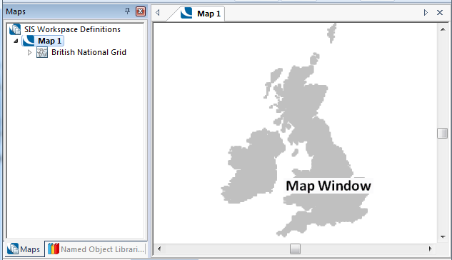
The Map Window displays graphical items in 2D. The Map Window is the normal display window for all graphical items.
The View [Document Views] buttons create new Map Windows as follows:
Map [View-Document Views] creates a new Map Window directly. From extents [View-Document Views] allows you to draw a box over an area of a map in the Map Window, on completion a new Map Window will be displayed showing the extents of the box:
When two or more Map Windows are open the windows can be tiled horizontally or vertically from the Map tab local menu:
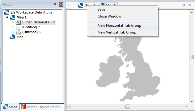
New Horizontal Tab Group:
New Vertical Tab Group:
Cadcorp SIS has many different ways to pan and zoom the Map Window. There are several commands, e.g. In [Home-Zoom], Out [Home-Zoom], Drag [Home-Pan], Roamer Mode [Home-Zoom], that allow you to use the mouse to change the view. These commands cannot be run at the same time as other commands which use the mouse, e.g.LineString [Create-Simple].
If you want to change the view while using another command, then you can use one of the following methods:
Pressing the middle mouse button (wheel), where available, lets you pan the view in the same way as using Drag [Home-Pan].
Spinning the mouse wheel, where available, zooms the Map Window in or out, depending on the direction of the spin.
The '+' and '*' keys zoom in and out, respectively. Note that '*' is used instead of '-' because '-' is required for typing co-ordinates into the Position Bar.
Each map window has slider bars for panning the view horizontally (East/West if the map has not been rotated), and vertically (North/South if the map has not been rotated).
Pressing the cursor keys shifts the view in the direction of the arrow. If you have a full numeric pad the PgUp, PgDn, Home and End keys can be used to pan north-east, south-east, north-west and south-west (make sure you are operating with NumLock off):
The default scrolling step in all directions is 8 pixels. You can change this by holding down the Shift and/or Ctrl keys in combination with the scrolling keys as follows:
| Shift |
1 pixel |
| Ctrl |
64 pixels |
| Shift + Ctrl |
half window height and/or width |
* and + Keys
Use the multiplication key (*) on the numeric pad to zoom out, and the plus key (+) to zoom in, doubling or halving the area of map displayed. These functions work only on the numeric pad. The * and + keys on the main area of the keyboard do not work in this way.
When working with multiple windows, you may zoom or pan in each single window independently, but you may have to select the window you require before carrying out the operation.
In each of the windows except the current window, an outline is drawn to show the extents of the current window (as long as the current window’s extents lie within that window):
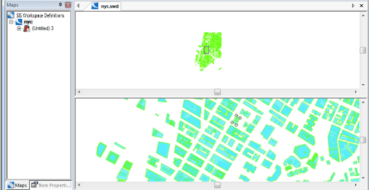
The outline will normally be a rectangle (as shown above), but it could be a distorted quadrilateral if the view Coordinate Reference Systems are different, or a cone if the current window is 3D.
You can use one window as a reference view for another when panning or zooming.
For example:
If Window 1 displays a large part of a residential area at small scale, while Window 2 is zoomed in to look at just a few of the houses. You now want to change the view in Window 2 to look at a few houses in a different part of the same residential area. Use Window 1 as a reference view in which to select the new area to be viewed in Window 2:
Recentre [Home-Pan] allows you to specify the centre of one map window by clicking in another map window.
The Zoom commands, accessed from the Home tab, are transparent commands. This means you can use any transparent command while you are in the middle of another command, without the need to cancel or complete the command.
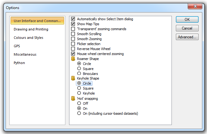
To select this feature, choose the ‘Transparent’ zooming commands option in the User Interface and Commands area of the Options dialog, seeSystem Options.
![]()
For example, suppose you want to measure the distance between two points that are far apart on the map. You could zoom out so that you can see both points on the screen at the same time, but then you might find it difficult to select them accurately if the display scale is small. Using transparent commands, you could follow this procedure:
Similarly, you can use the transparent Zoom commands while you are in the middle of constructing graphics, such asLineStringitems.
You can use Roamer Mode [Home-Zoom] another transparent command, while you are in the middle of a measure or construction command. The Roamer gives you a magnified view of the graphics immediately beneath the pointer. See the Home tab Zoom commands.
The Map Window and corresponding Table Window are dynamically linked. Therefore by displaying both windows simultaneously you can highlight a row or rows from the table window, then use Selection [Home-Zoom]to zoom the map window to the extent of the selected item or items.
Similarly if you select an item in the map window, the corresponding row in the table window will become highlighted (you may need to use Scroll Dominant [Table-Table] to see it). Additionally, if the Flicker Selection tickbox is checked in the User Interface and Commands area of the Options dialog (shown above) the selected item flickers on the screen until deselected.
Keyhole zooming is a useful technique for viewing an area of an overlay that lies below another overlay. For example, if you have a vector map of a region and a raster bitmap of the same region lying on top of it, you can use keyhole zooming to make a temporary hole in the raster bitmap to see the vectors below it, ‘through the keyhole’.
The following diagram shows how the lower overlay, which is called the keyhole overlay, can be seen through the hole in the upper overlay, even though the rest of the lower overlay is hidden by the opaque bitmap above it.
To use this technique, first choose .gif) Set Keyhole Overlay [Home-Zoom] to set the keyhole overlay. The Keyhole Overlay dialog lets you specify which overlay is to be viewed through the keyhole.
Set Keyhole Overlay [Home-Zoom] to set the keyhole overlay. The Keyhole Overlay dialog lets you specify which overlay is to be viewed through the keyhole.
Once the keyhole overlay has been set, choose .gif) Keyhole [Home-Zoom] to view the result.
Keyhole [Home-Zoom] to view the result.
The shape of the keyhole may be changed in the User Interface and Commands area of the Options dialog, see System Options.
The keyhole Shape choices are:
There may be times when the screen image appears with parts of the graphics missing. This can happen when graphics have been moved or deleted, or after using the cursor keys to pan across the map base.
Text and point items are not always redrawn immediately, and can appear incomplete. This is because they have only one reference point for locating them on screen, and in some circumstances, if that point is on screen already, SIScannot know that the rest of the text or point item needs redrawing.
Use the Redraw [Home-Map] (F5) to refresh the current window, or .GIF) Redraw All Windows [View-Window] to refresh all windows.
Redraw All Windows [View-Window] to refresh all windows.
During a long redraw you can halt the operation by clicking on the Cancel button which appears on the status bar at the bottom of the screen, or by pressing Ctrl + Break.
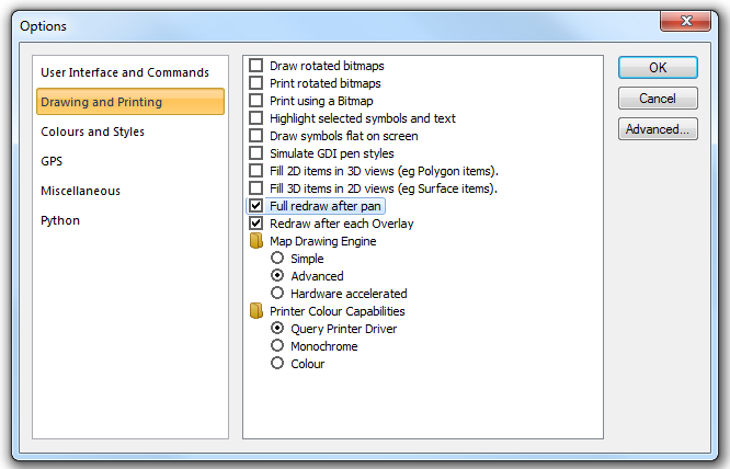
There are some preferences which give you more control over the redrawing of map windows. One preference, available in the Drawing and Printing tab of the Options dialog is Full redraw after pan, this forces SIS to redraw the Map Window after a pan operation. Another preference, Redraw after each Overlay, forces SIS to redraw the Map Window after each overlay has been loaded:
If you want to return a rotated view to its original rotation, accept the angle you are prompted with in the Angle dialog.
Point text with the Horizontal property set to True will always remain horizontal, even when the view is rotated.
Note this feature only works with point text.
You may store any view which is currently on screen, giving it a name by which to recall it later. Views are named objects, and newly-created ones are stored in the current library. See What is a Named Object Library?
Note: A view’s local menu in the Libraries Control Bar allows you to delete or rename the view, copy it to the clipboard (for pasting into other libraries), or see its properties (its projection and scale).
Once a view has been stored it can be recalled using the Recall [View-Map Views]. A zoom and pan are automatically carried out so that the stored view fills the current window.
Send comments on this topic.
Click to return to www.cadcorp.com
© Copyright 2000-2017 Computer Aided Development Corporation Limited (Cadcorp).