 Symbol Symbol
.gif) Symbol creates a named Symbol from selected items.
Symbol creates a named Symbol from selected items.
Symbol objects are used to define the appearance of Point items, and provide a means of placing symbols.
You may use Bitmap items as part of Symbol objects, but it is recommended that you use small Bitmap items, to save memory and speed up later drawing.
You can create symbols using SIS Map Editor and Map Modeller.
The sub-topics detailed on this page are:
Notes on Symbol component levels
The levels of the items used to define a Symbol are remembered in the Symbol definition, so you can reliably define their drawing order. This is useful when the Symbol contains opaque Polygon and/or Bitmap items. This is explained in Notes on Symbol component levels on this page.
If any items inside the Symbol have the special "By Overlay" Pen or Brush style, then the Symbol will substitute the Point item's Pen or Brush. (Remember the Symbol will be assigned to Point items later). This means that you should consider the Pen and Brush settings of the items making up the Symbol, and decide whether you want the Symbol to change its colour later on or not.
First construct or select the graphics which will make up the new Symbol, then select this command. You are prompted for the centre of the Symbol. Snap the point (which does not have to be on the graphics) which you want to be the origin of the Symbol, i.e. the point by which the Symbol will later be placed. You are then prompted for a name. The Symbol will be stored by this name in the default Named Object Library.
A Symbol may consist of any combination of LineString items, Polygon items, box text and bitmaps (but not point text and topological structures; although you can use these items, they will not be displayed).
Symbols can be extremely complex objects, making extensive use of the advanced capabilities of SIS such as scale thresholds and levels. For example, it is possible to create symbols which appear differently at different scale thresholds.
After a Symbol has been defined it may be assigned to any editable Point item using Properties [Home-Selection]. Hittable or visible points may be displayed as a Symbol by setting a Symbol override on the overlay using Overlays [Home-Map].
The Level of the Symbol's original items determines the drawing order of the components of the Symbol every time it is drawn. This means that you can define a Symbol made up of Polygon items that use opaque Brush objects. By carefully setting the Level of the Polygon items you can ensure that you get the overlapping effect that you want. Using Polygon items (or Bitmap items) in Symbol objects is especially useful for symbols that stand out, e.g. for Command and Control type applications.
When symbols are drawn on Points, the levels are added together. SIS will only draw levels between 0 and 255. If the total of the levels is greater than 255 the symbol is not drawn.
When arriving at a total number for the levels each individual layer of the Symbol is taken into account.
The following examples illustrate this:
It is recommended that items making up a symbol are set to a low level to avoid the possibility of all, or part, of the symbol not being displayed, as shown above.
This will make the symbol display at its created size, or a factor of its created size as required.
To ensure the Symbol is displayed at the correct scale go to the Overlays dialog Styles tab and enter a value of -1 in the Scale Overrides-Point textbox:
.gif)
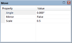
This sets the Point scale override property (_pointScaleOverride# attribute) to -1. This may be observed by clicking the Properties button in any of the Overlays dialog tabs (except Preview) to display the Overlay properties:
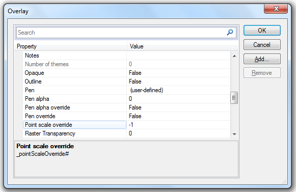
Point scale override is a built-in property in current versions of SIS and does not need to be added as was required for previous versions of SIS.
With Point scale override set to a value of -1 (minus one) the symbol will be displayed at its true size. This refers to the size of the symbol when it was created. For example the standard circle symbol in SIS was created to be 10mm in diameter, SIS will display a 10mm circle symbol when the _pointScaleOverride# value is set to -1. If the value is set to -0.5 the symbol will be displayed at half its true size. If the value is set to -2 it will be displayed at twice its true size, -4 will display the symbol at four times its true size, etc.
Note: The Point scale override property for SIS versions prior to 8.0 was GPointScaleOverride#. However, if an SWD from an older version of SIS (where GPointScaleOverride was used) is opened in the current version of SIS the GPointScaleOverride# property will be converted and shown as _pointScaleOverride#. If a GPointScaleOverride# attribute is added (using the Add button in the above dialog) it will not be added to the property list but the value of the property will be assigned to Point scale override.
Ordnance Survey files contain locations for symbols of ordnance benchmarks, pylons, flow arrows, etc. These Ordnance Survey symbols are stored with appropriate names (e.g. Bench Mark, Pylon, Flow Arrow) in the OS DNF, OS NTF and OSNI NTF folders in the (standard) library.
The method of placing a Symbol is fully explained in Point [Create-Simple].
Top of page
Send comments on this topic.
Click to return to www.cadcorp.com
© Copyright 2000-2017 Computer Aided Development Corporation Limited (Cadcorp).