Creating your own Backdrops for KeyMaps
The command Quick Print Template [File-Print Template] uses a Print Template Wizard to take a Map Window or a 3D Window and place the picture inside a Print Template.
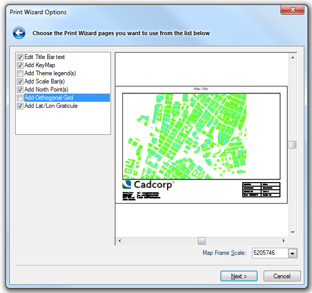
The command Print Template [File-Print Template] allows you to choose which Print Template to use, and at which scale (when used with a Map Window), what "furniture" to add (e.g. a Scale Bar, a North Point, a Key Map, etc.), and whether to just print the results, or to create a new SIS Workspace Definition (SWD) for further editing.
The Quick Print Template command is a simplified version of the Print Template command.
Make sure the current window contains the view that you want to print.
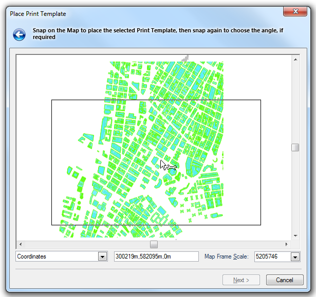
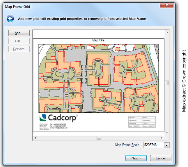
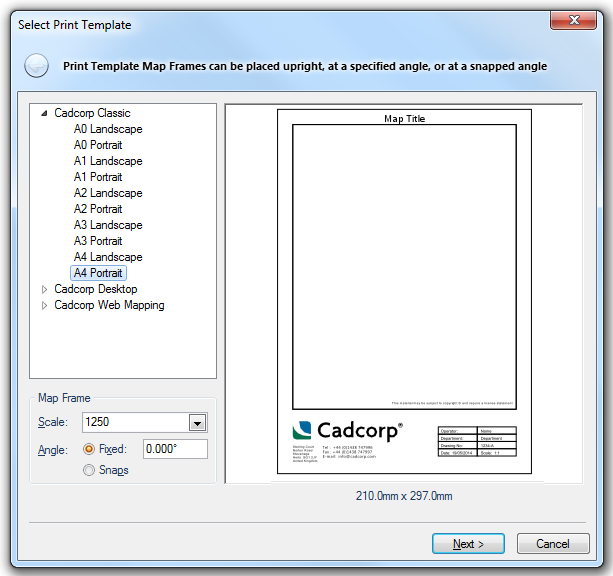
The inner rectangle on the print template is called the "Map Frame", this is the area where your map will be placed.
- Change the Scale if required.
- Change the Angle of rotation if required. You may want to do this, for example, to align a major road or building horizontally on the paper. You have two options:
- Fixed - Type in the angle required. North is 0°, East is 90° etc. The print template is rotated anti-clockwise. For example, if you type an angle of 90°, East will be pointing up. Note that when you come to place the print template on the map base, it will appear to be rotated in the opposite direction. This is because the map graphics are to appear rotated once the print template is aligned back with the sheet of paper.
- Snaps - When you later place the template, this option will require you to give an extra snap to indicate interactively the angle of rotation.
View of map in the current window, showing the print template rectangle at a scale of 1:1250, rotated at an angle of 72°:
The resulting print template:
.png)
If you do not see the Place Print Template dialog, proceed to step 5.
If you do see the Print Size dialog then the print template you have chosen does not fit onto the current printer paper at the scale you have chosen. You can:
- go back a step and choose another print template.
- choose Print Setup [File-Print] to access the Print Setup dialog to change the paper used.
- click on Fit in the Print Size dialog to fit the template to the paper. In this case the stretch factor to be applied to the Print Template to make it fit onto the current printer page setup will be shown:
- press Next to continue.
If you cannot see the rectangle, it is either bigger than the view or very small. Zoom out or in until you can see it using the “+” or “*” keys on the numeric keypad, the mouse wheel, the Up, Down, Left or Right arrows, or return to the first page to choose a different scale or print size.
Click Next.
The Title Bar text field can contain your own information for the print.
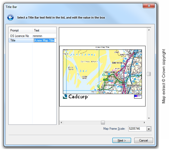
To change the title to your own requirement select Title in the Prompt column and press F2 to highlight the title text for editing. Make the change and press Enter when complete.
Click Next.
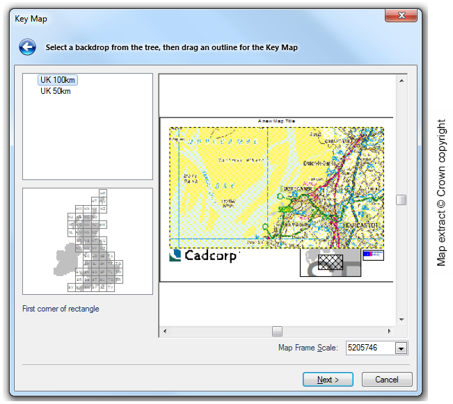
A KeyMap gives a visual indication of the spatial location of the area being printed. It displays a polygon representing the area of map printed, superimposed on a larger area (the backdrop).
SIS provides two backdrops for the UK: one based on 100 kilometre squares, the other on 50 kilometre squares. These are stored as named items in the (standard) library. If the scale of the backdrop is too large in comparison to the map being printed (e.g. a backdrop with scale 1:10 000 000 and a print map with scale 1:3000), the backdrop will appear as a blank rectangle in the print template.
Click Next.
Note: Clicking on Toggle ‘*’ Objects (local command on the Libraries Control Bar, Libraries item), will toggle the display of the *KM folder.
For details of creating (and copying) your own backdrops for KeyMaps see Loading maps (and other data files).
This option is available only where you are using themed overlays, or overlays and datasets which use Cadcorp Feature Tables. It allows you to place theme legends on the template.
If you wish to add a theme legend to a previously created template, you can do so using the Map Frame's local command Legend.
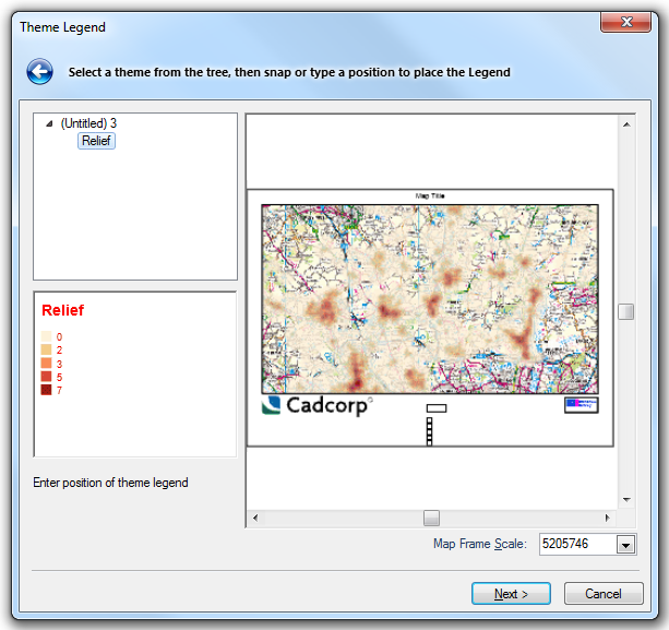
Click Next.
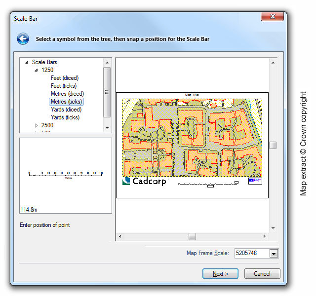
If you wish to add a scale bar to a previously created template, you can do so using the Map Frame's local command Create Scale Bar.
- Click the position on the template where you want to place it.
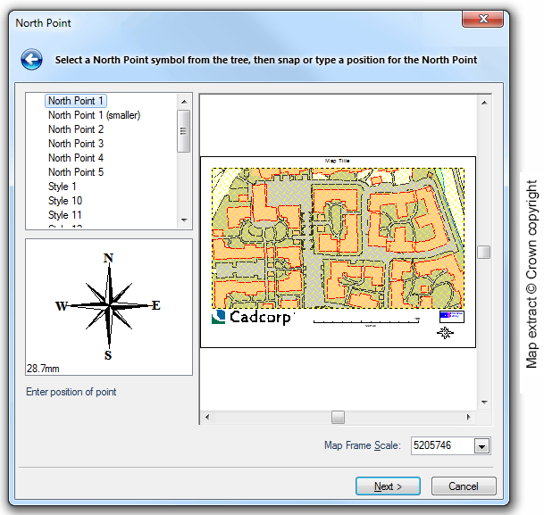
- If you make a mistake in placing the North Point, click on Back to go back a step, then Next to return to this option.
If you wish to add a north point to a previously created template, you can do so using the Map Frame's local command Create North Point.
This option allows you to show eastings and northings by means of grid lines and/or annotation.
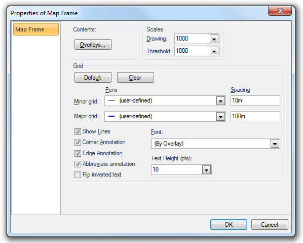
The Properties of Map Frame dialog is the standard properties dialog for map frames, and allows you to change other parameters as well as those of the grid. You can choose:
When deciding how the grid lines should appear, you can choose:
- the Pens and their Spacing to be used for both Minor grid and Major grid lines
- whether the grid lines are shown, or just the annotation (Show Lines)
- whether annotations are displayed along the edges (Edge Annotation), and whether the special annotation given at the corners is shown (Corner Annotation)
- the appearance of the annotation text (Text Height and Font)
- whether annotations are shown in full, or abbreviated so that only the changing portion of edge annotation is shown (Abbreviate annotation)
- whether text, which would normally appear upside down when viewed from the bottom of the map frame, should be flipped (Flip inverted text)
Most of the options you specify here become properties of the map frame and can be changed later in the map frame’s Properties dialog.
If the map frame contents have been rotated, the grid lines will be correspondingly rotated. Rotation angles between 0° and 45° will display eastings along the bottom and top of the map frame. Angles between 45° and 90° will display eastings along the left and right sides.
Grid lines will always be drawn on top of the map frame contents.
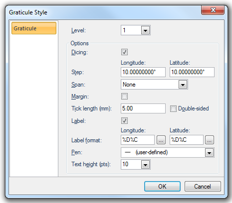
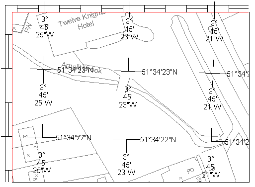
This option enables you to display a lat/lon graticule and define how it will appear. Each graticule can consist of up to 8 levels, each level being a sub-division of the previous level. For instance, level 0 (the first level), defines the appearance of the lines of latitude and longitude, and that of their labels. Level 1 defines the spacing of the dicing, and how it is labelled, and so on.
Graticule styles are named objects, stored in libraries.
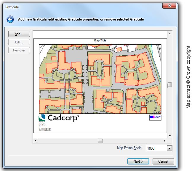
See Graticule parameters for further details.
If you want to add a graticule to a previously created template, you can do so using the service local command Create Graticule.
Once you have created a graticule on a print template, you can save it for future use, using its item command Store style.... You can select a graticule using the S snap.
Graticules are named objects, and are stored in the current library.
The following parameters are detailed in this section:
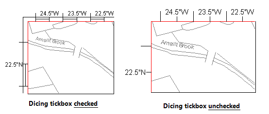
Here you choose whether or not to display dicing. This parameter can only be set in level 1.
These are the intervals at which the graticule lines will be drawn, in the current angular units
The span determines how the graticule lines are drawn at this level. There are four options:
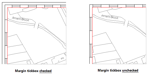
Margin
Use this option to determine whether or not a margin is drawn at this level.
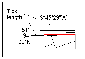
This is the distance that the ticks which appear on the graticule border (at the step intervals) extend beyond the graticule border.
Ticks are always drawn perpendicular to the graticule border (whereas span lines are drawn along lines of equal latitude or longitude).
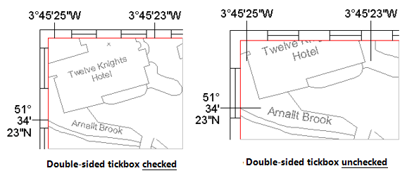
By selecting the Double-sided checkbox, the tick lines are drawn on both sides of the graticule border.
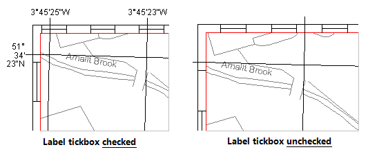
Use this checkbox to control whether or not to have the graticule ticks labelled:
At each level you can choose whether to show degrees, minutes, seconds and the compass point. The options are:
%d or %D print the degrees (%D appends a degrees symbol)
%m or %M print the minutes (%M appends a ')
%s or %S print the seconds (%S appends a ")
%c or %C print the direction (N, S, E, or W)
%d, %D, %m, %M, %s and %S can be modified to print fixed width and precision. For example, %4.2s will print at least 4 characters, with 2 decimal places.
The pen used for the graticule lines and the labels. Use the More button to edit the current pen using the Edit Pen dialog.
This is the point height of the label text and/or the graticule span text.
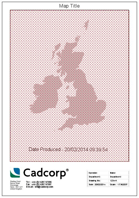
A Point/Box/Box Label Text item can be added to a Print Template to automatically show date and time details.
The following line of code entered in a Point Text/Box Text/Box Label text box:
Date Produced - ^(FormatDate(date(),"%x %X"))
would produce an automatic date and time for the current locale in the following format, as shown above.
Date Produced - 20/02/2014 09:39:54
See Property Expression Syntax for a full list of codes that may be used with the FormatDate routine.
Send comments on this topic.
Click to return to www.cadcorp.com
© Copyright 2000-2017 Computer Aided Development Corporation Limited (Cadcorp).
 Stretch by.gif)