About Print Templates
Introduction
Creating a print template
Creating a KeyMap
Using point text
Creating a scale bar
Creating a north point
Creating a logo
Creating symbols
Introduction
A Print Template is a pre-formatted page layout, which, as well as the view of the map can also include other "furniture", e.g. page borders, logos, Scale Bar, North Point, Graticule items, etc. The view of the map is defined using a Map Frame item.
SIS has a number of default Print Templates: Landscape or Portrait A0, A1, A2, A3 and A4 sizes. These are stored in the read-only (standard) library. They show the Cadcorp logo and address, and the Ordnance Survey logo and copyright notice.
SIS provides you with the choice of two Print Template commands to help you with the process of creating and using print templates:
Back to top of page
Creating a print template
You can create a Print Template by editing an existing Print Template, or by creating one from scratch.
Creating a new print template from an existing print template
- Select Recall Print Template [File-Print Template].
- In the resulting dialog, select the Print Template which most closely matches the size and style you wish to create.
- The Print Template graphics will be copied into a new SIS Workspace Definition (SWD) named according to the template name.
- Edit the copied Print Template graphics, e.g. to change text or logos, add "furniture", etc.
- Select Store Print Template [File-Print Template], choose a folder and rename the Print Template.
Note: Before you store a Print Template ensure that you have zoomed to a suitable extent to contain the template graphics. For example, before storing an A4 Portrait template, create a 210mm x 297mm rectangle around the template graphics. Zoom to the extent of this, then remove the rectangle, or change its Pen and Brush to Blank. The extent of the template is used when printing or when exporting to PDF.
Creating a new print template from scratch
- Select New [File-New] and select Blank Map Document from the File Types dialog to create a blank SWD.
- Select CRS [Home-Map] and set the Coordinate Reference System and Viewing Projection to Paper.
- Open an existing SWD, or create a new SWD which is typical of the maps for which you will use the Print Template.
- Right click on either of the SWD tabs and create a new tab group (either horizontal or vertical).
- Make the Map Window containing the new Print Template graphics current.
- Select Map Frame [Create-Miscellaneous], and click in the map base window. A rectangle the shape of the view in the map base window (not the shape of the map window) will be placed on the cursor in the Print Template window. You may not be able to see this rectangle because it is either too large or too small. Try zooming in and out until you can see the rectangle on the cursor. If it is too large or too small then press Escape to exit the command and choose a more appropriate scale before starting Map Frame [Create-Miscellaneous] again.
- After placing the Map Frame item you can close the map base window. You will see that the Map Frame item still draws its contents properly, even though the original window has been closed.
- Resize the Map Frame as required, and add any Map Frame "furniture", an other graphics, e.g. text, logos, etc.
- When you are satisfied with the new Print Template, select the Map Frame item and choose Properties [Home-Selection]. Press the Overlays... button and remove all of the Map Frame overlays.
Note: Before you store a Print Template ensure that you have zoomed to a suitable extent to contain the template graphics. For example, before storing an A4 Portrait template, create a 210mm x 297mm rectangle around the template graphics. Zoom to the extent of this, then remove the rectangle, or change its Pen and Brush to Blank. The extent of the template is used when printing or when exporting to PDF.
- Select Store Print Template [File-Print Template], choose a folder and give the Print Template a name.
Back to top of page
Creating a KeyMap
In the Libraries Control Bar, display the *KM folder within Item in the standard library, copy the folder and paste it into the temporary library.
Copy and paste the backdrop item into the *KM folder in the temporary library. The backdrop will now be listed as a KeyMap when you use Print Template [File-Print Template] or Quick Print Template [File-Print Template] or use KeyMap [Paper-Annotate] on a Map Frame item in a Print Template.
For full details of KeyMaps and backdrops see Loading maps (and other data files).
Back to top of page
Using point text
Point Text can be used to create Prompts that are visible and the Text editable from the Print Template Wizard.
Use Point [Create-Text] and place on the Print Template where required. Use Properties [Home-Selection] and add “Prompt” of type String to the Attributes tab with the text required to be displayed in the Print Wizard as a Prompt as the Value e.g. Title. In addition on the Text tab a default description can be added which is visible on the Print Template until amended by the user e.g. A Cadcorp Map.
Point Text can also be used by an expression to auto-populate the Print Template. Construct the Text Point as above and add the expression to the Text tab. Some useful examples:
Map Frame Item Scale: 1:^(ItemId._photoscale#)
ItemID can be found in the Map Frame’s Properties, and will therefore be different for each Map Frame on an individual Print Template. For all Cadcorp created Print Templates the first ItemId will be 59 and so the expression is:
1:^(59._photoscale#)
Today’s date: ^(FormatDate(Date(),”%d.%m.%y”))
Or current year: ^(FormatDate(Date(),”%Y”))
Back to top of page
Creating a scale bar
Scale bars are themselves scaled, based on the scale factor assigned in a print template wizard. So, when creating scale bars, remember that real coordinates are used, i.e. centimetres, inches, metres, and so on, using a Paper projection.
Creating a scale bar is similar to creating a print template, because there are several default scale bars in the SIS (standard) library.
Note: It is recommended that a scale bar is created in paper size at scale 1:1, also ensure the dataset scale is set to 1.
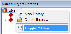
To create a scale bar based on an existing one, follow these steps. Before you start, use the Toggle ‘*’ Objects command on the Libraries Control Bar's default local menu so that you can see the *SB folder.

- Locate a scale bar similar to the scale bar you require.
- Copy it into the current library.
- Once copied, rename the *SB folder to SB to allow editable access to the library.
- Set up an SWD with the Paper projection.
- Choose Point [Create-Simple] and choose the scale bar that you require (from the SB folder).
- Insert a scale bar point.
- Select it, and, from its local menu, choose Explode Symbol. This changes it into its component parts.
- Edit it by changing text values, size and colour, and the dice or tick marks.
- Other useful commands for editing scale bars are Divide Distance [CAD-Divide] to divide a line into segments, and
.gif) Measure Distance [Home-Measurement] to confirm the scale bar lengths.
Measure Distance [Home-Measurement] to confirm the scale bar lengths.
 an edited scale bar for a 1:1250 map | |
There is no ‘correct’ way to create scale bars. In general, however, the main scale runs to the right and the extension scale (which is in smaller units) runs to the left. More than one type of scale can be used on a map (e.g. miles and kilometres).
- Finally, to save the scale bar and put it into the scale bar folder, select all the parts of the scale bar and choose Symbol [Create-Miscellaneous]. Click on the point for the symbol centre, and, when prompted for a folder and name, use the *SB folder and give the scale bar a new name. The scale bar appears in the Print Wizard options.
- Remember to save this in a named library if you want to use it again.
Back to top of page
Creating a north point
North points can be created in a similar way. Before you start, use the Toggle ‘*’ Objects command on the Libraries Control Bar's default local menu so that you can see the *NP folder.
- Set up an SWD with the Paper projection.
- Draw your north point. Remember to think about the size of the point in relation to the map on which it will be put.

| a customised north point
|
- Finally, to save the north point and put it into the north point folder, select all the parts of the north point and choose Symbol [Create-Miscellaneous]. Click on the point for the symbol centre, and, when prompted for a folder and name, use the *NP folder, and give the north point a new name. The north point appears in the Print Wizard options.
- Remember to save this in a named library if you want to use it again.
Back to top of page
Creating a logo
Normally a company logo will be saved as a point, although a bitmap can also be used.
Back to top of page
Creating symbols
Using a bitmap
- Find the bitmap/icon you want to use.
- Open it in SIS in a new SWD using the Paper Projection. When adding the New Overlay use the Import file(s) option so that you will be able to edit the file. See Loading Maps.
- Select the bitmap. Make it the correct size by manually moving/resizing it using the grab handles. At the bottom of the screen is the width of screen information which will help. Remember: this is the size that you want the symbol to appear when printing the map at the same scale as the overlay scale.
- Once you are satisfied, select the item and go to Symbol [Create-Miscellaneous].
- Click somewhere on the item. This is the point at which the symbol will be orientated. The usual place would be the centre of the item.
- You will be prompted for a name for your symbol. This will be saved into the current library.
- Your item will appear in the Symbol drop down list. You can close the SWD containing the original bitmap without saving.
Using items
- Open a new SWD in SIS with a Paper Projection.
- Size the screen to the size you want your symbol to appear.
- Draw your symbol using the Draw toolbar. You can draw using MultiPolygons, MultiLineString items, or points and your own pens and brushes.
- Select all the items which make up your symbol and carry out steps 4 to 7 above.
Top of page
Send comments on this topic.
Click to return to www.cadcorp.com
© Copyright 2000-2017 Computer Aided Development Corporation Limited (Cadcorp).

.gif) Measure Distance [Home-Measurement] to confirm the scale bar lengths.
Measure Distance [Home-Measurement] to confirm the scale bar lengths.
