.gif)
This quick start page briefly describes some of the commands provided by products in the SIS suite:
Some of the options described in this topic may not be available on your system, depending on the product that you are using. For more details of each go to the For further information links.
The SIS user interface can be viewed in a range of styles, depending on your preference. The Styles can be changed using the Style [View-Cadcorp SIS] command. The styles available are shown in the description of this command. The Screen shots used in this Help are the Scenic/Microsoft Windows 7 style with the Mouse layout selected.
The main window contains the Ribbon tabs, Quick Access Toolbar and different types of windows, including Control Bar Windows, Map Windows, Table Windows, 3D Windows and a Microsoft Bing Maps Window.
Many windows can be opened simultaneously. These can be different map windows or map windows together with their associated table window and/or 3D window.
.gif)
The initial display shows the main window with a single Map Window which may contain map graphics and your own graphical data.
Map windows can be split horizontally and vertically.
Ribbon tabs are shown at the top of the display. Clicking on each tab accesses the available ribbon options.
Further Information: Menu commands
The Quick Access Toolbar, part of the ribbon, is a small, customizable toolbar that provides access to frequently used commands independent of which ribbon tab is selected.
For further information see Quick Access Toolbar.
By default the Maps, GPS (Location), Item Properties and Libraries control bars are located to the left of the Main Window with the Developer control at the bottom of the Main Window. All of these control bars can be moved to other screen positions.
These control bars allow you to keep track of the following information:
Note: If the control bars are moved or resized their new positions and sizes will be stored in the Options database and will be remembered for subsequent SIS sessions.
For further information see What are the Control Bars?
Overlays are digital representations of real-world objects. An overlay usually consists of a collection of similar objects, such as roads, buildings, sales territories, flood zones etc. Overlays appear within the Map Window and are controlled within the Maps tab.
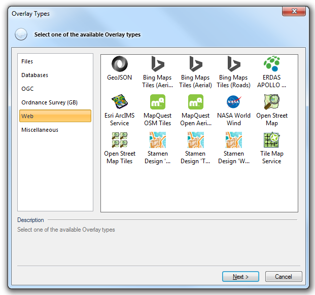
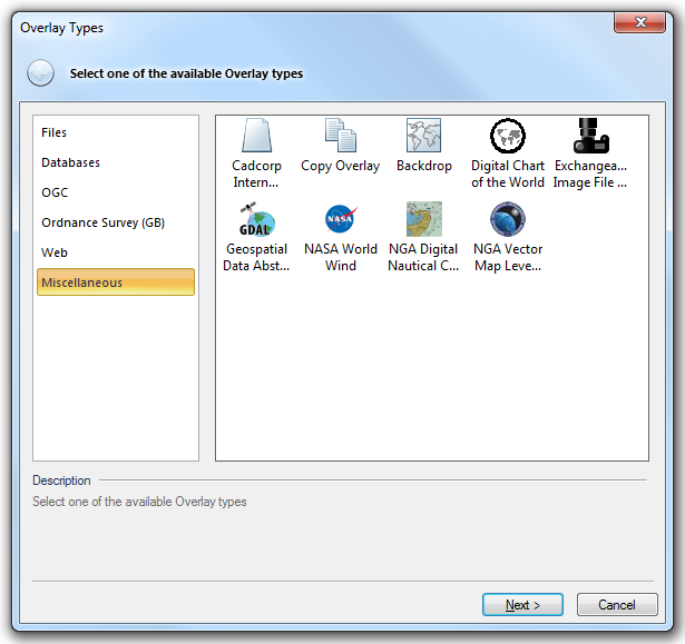
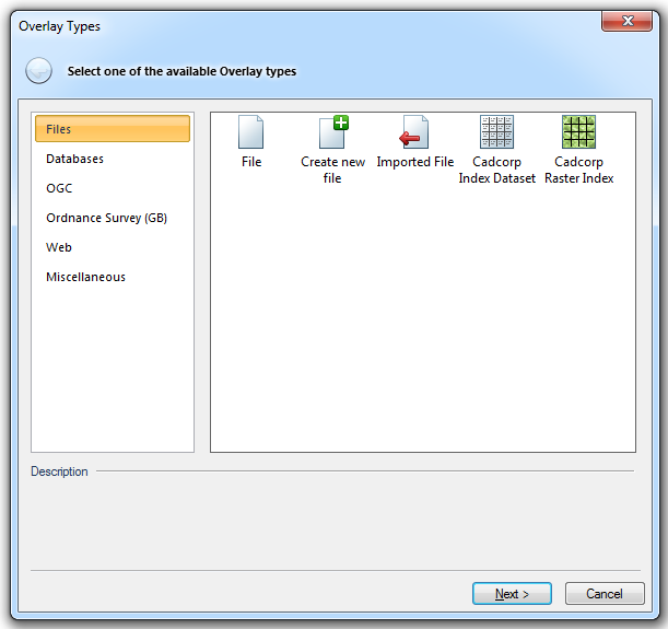
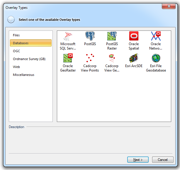
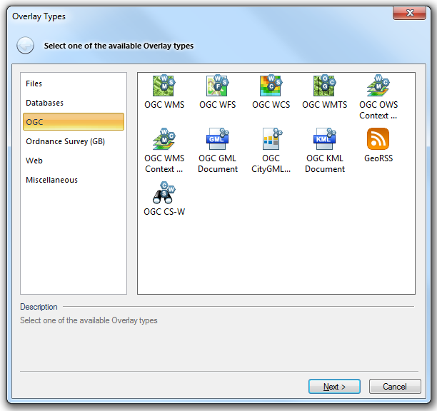
To add your data to the Map Window use the Overlay Types dialog accessed via Add Overlay [Home-Map]. Here you can choose any of the supported formats in SIS. These may be stored as files or in databases on your PC or network.
The Overlay Types are grouped as follows:
The Overlays are fully described in the Overlay Types topic.
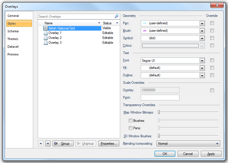
The Overlays dialog allows you to access much of SIS's functionality, including: changing the status of overlays; assigning scale thresholds; changing overlay styles; controlling what is seen in the Table View; and changing dataset details.
To display the Overlay dialog, do one of the following:
For further information see What is an Overlay.
SWD stands for SIS Workspace Definition. This SWD file represents a saved view of your data, in whatever condition you left it (editable, hittable, zoomed in, filters applied, etc). To save the SWD use Save [File-Save]. This will create a file with the extension .swd.
The automatic backup and autosave functions are inter-related and are both enabled or disabled from the Options [File] dialog, Miscellaneous tab:
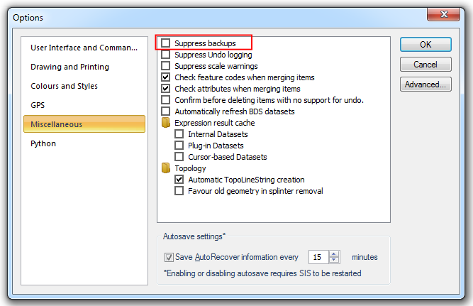
If the Suppress backups tickbox is checked no backups will be made.
Note: This setting does not affect the autosave function.
If the Suppress backups tickbox is unchecked and a SIS Workspace Definition is saved to a location using Save As [File-Save As] a backup will be made at pre-set intervals to the same location using the prefix "Backup of ....".
For example an SWD saved as "D:\Data\MyMap.swd" will have the backup file "D:\Data\Backup of MyMap.swd".
Note: If the Save AutoRecover information every tickbox is unchecked, then checking or unchecking the Suppress backups tickbox has no effect.
The number of minutes for both backup and autosave intervals are set in the Options [File] dialog, Miscellaneous tab:
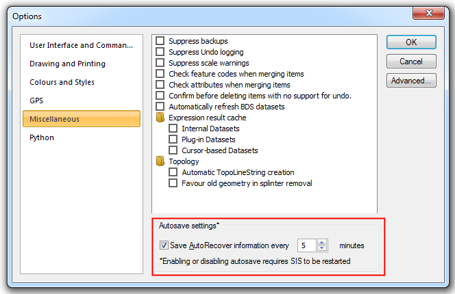
Checking the Save AutoRecover information every tickbox will cause SIS to make both autosave and backup operations (provided the Suppress backups tickbox is not checked) at the intervals specified in the minutes box.
Unchecking the Save AutoRecover information every tickbox will cause SIS to suppress both the autosave and backup functions.
Checking or unchecking the Save AutoRecover information every tickbox requires SIS to be restarted to take effect. However, changing the number of minutes (range: 1 to 120) takes effect immediately and does not require SIS to be restarted.
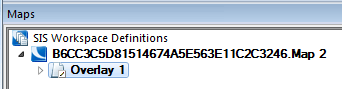
If a new SWD is created and not saved within a pre-set number of minutes SIS will give the SWD a temporary name in the form of an alphanumeric string appended with the default map name, for example: 5AF8E8AE881D45ecBF48FE16BEDAB787.Map 2.
The SWD will autosave automatically at intervals, set in the Autosave settings area of the Options [File] dialog - Miscellaneous tab, to the "AppData\Local" folder, for example:
C:\Users\smithj\AppData\Local
The alphanumeric string preceding the default map name, in this example Map 2, will change each time the autosave function is carried out. After the first backup the autosaved file name will not bear any similarity to the alphanumeric string shown in the Maps Control Bar.
SIS does not remove autosaved files from this folder. It is recommended that these files are deleted from the folder from time to time when you are sure they are no longer required.
It is recommended that Save As [File-Save As] is used as soon as possible to save the SWD with a more meaningful name.
There are many tools for moving around in the Map Window. These are located in the Pan and Zoom areas of the Ribbon Home tab. Other options for navigating in your map include: the plus key (+) on the number pad (with the Map Window active) to zoom in; the multiplication key (*) on the number pad to zoom out, the wheel on an Intellimouse to zoom in and out; the Map Window scroll bars; the cursor keys (Up, Down, Left and Right arrows); and the Page Up (move north east), Page Down (south east), Home (north west) and End (south west) keys.
The Developer Control Bar is displayed by default at the bottom of the Map Window. This control bar can be moved to any position on the screen, inside or outside of the SIS Main Window.
For further information see Zooming and Panning using the Mouse and Keyboard
A Coordinate Reference System is a method of projecting positions from the curved surface of the Earth to a flat screen or paper. Because of this curvature paper maps will always be slightly distorted. Different coordinate reference systems are designed to minimise the distortion in different ways. Some coordinate reference systems show orientation accurately, some show areas accurately etc.
Use CRS [Home-Map] to select the desired coordinate reference system. If you are working on UK data, this is most likely to be OSGB 1936.British National Grid. If you are using Ordnance Survey data, when you open these overlays the map should default to OSGB 1936.British National Grid. Using the Units tab you can change the default display method for the units on screen.
For further information see Coordinate Systems and Coordinate Reference Systems, Coordinate Reference Systems, Coordinate Reference Systems in detail.
To create items on your map first you need to create a file to put your data in. Use Add Overlay [Home-Map]. and choose Create New File from the Overlay Types dialog. This allows you to save a Cadcorp Base DataSet File (*.bds) or a Cadcorp Feature DataBase file (*.fdb) to a known location, either on your hard disk or onto the Network. Once you have created the file, to add it to a new SWD use Add Overlay and select the File option.
Once you have created and saved your file, you can use Export to file [File-Export] to export it in the format of your choice.
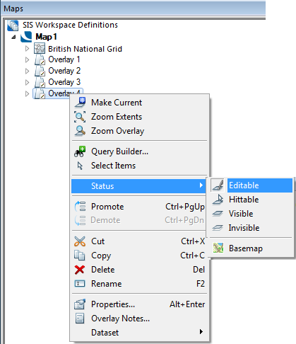
Once a file has been created you need to make it Current so that any data created goes into that file. To make an overlay Current right click on the name of the overlay and in the local menu that appears choose Make Current (at the top).
Local commands are displayed when the user presses the right mouse button while hovering over a specific part of the interface. For example, if you right-click on an overlay in the Maps Control Bar you can access processes that correspond to displaying overlays such as whether it is editable or hittable, or whether there is a filter applied to it. If you right mouse click over Themes of the same overlay you will see the local menu with processes relating to Themes such as Add Theme and Paste Theme.
You must Select items before you can carry out any process on them, such as changing their Pen or Brush.
To Select an item, first make sure that the mouse displays the default “Pointer” arrow ( ). If the mouse does not show this (e.g. the mouse is displaying the Roamer, or the Construct spanner) then press the Escape key. Left click on the item you wish to select. If there is more than one item close to the point at which you left-click, the Select Item dialog may appear. Using this you can scroll through the available items by pressing the Previous or Next buttons. To choose the item to select press OK (in the example below there is a rectangle with an overlapping circle and the mouse is pointing to both).
For further information see Selection Overview and Selecting Items
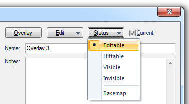
The status of an overlay refers to whether you can see that overlay, and whether you can change or edit that overlay. There are four overlay status conditions:
You can change the overlay status either by:
or
You can also toggle the overlays "on" and "off" by left clicking on the icon to the left of the overlay name in the Maps Control Bar.
If a cursor is near to an item you will see some text appear. This might read Line, or Vertex. These are snap-codes and allow you to snap to editable or hittable items in the Map Window. By left clicking when you are in the Construct mode (the cursor changes to a spanner) when you see the word appear you will snap automatically to the graphic. You can also use the relevant key on the keyboard, instead of left clicking, to snap to graphics (in the above example, you would use L to snap to the Line or V to snap to the Vertex).
For further information seeSnapcodes

SIS has many tools for creating graphical items. Some of these are found in the Ribbon Create tab, in the Simple group:
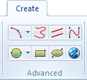
Some are in the Ribbon Create tab in the Advanced group, these are:
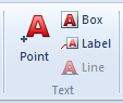
Tools to create text are in the Ribbon Create tab in the Text group:

SIS has the ability to measure various components of an item, its length, angle, position, route, etc. You can access these commands from the Ribbon Home tab Measurement group.
For further information see Querying data in the Map Window.
The Table Window is a tabular view of the current SWD in a new window. It shows all the columnar values assigned to items. If there are no data columns assigned to the items, Cadcorp will give them default values of: Description, Item ID, Item class, Origin X, Origin Y and Origin Z, for example:
You can add new, or remove existing values, from the Overlays dialog, Schema tab, Column drop down Add button. To show different tables for different overlays, use the pull-down menu at the top left of the Table Window. Go to the Maps Control Bar overlay Schema to turn the columns in the Table Window "on" and "off".
For further information see Overlay Data Schema
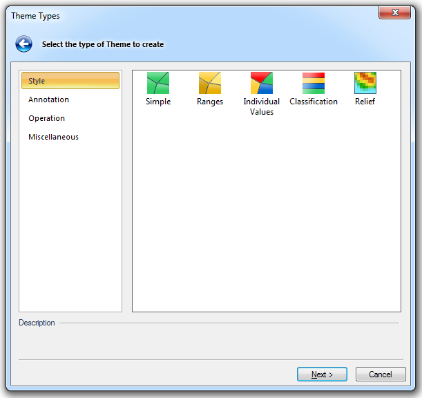
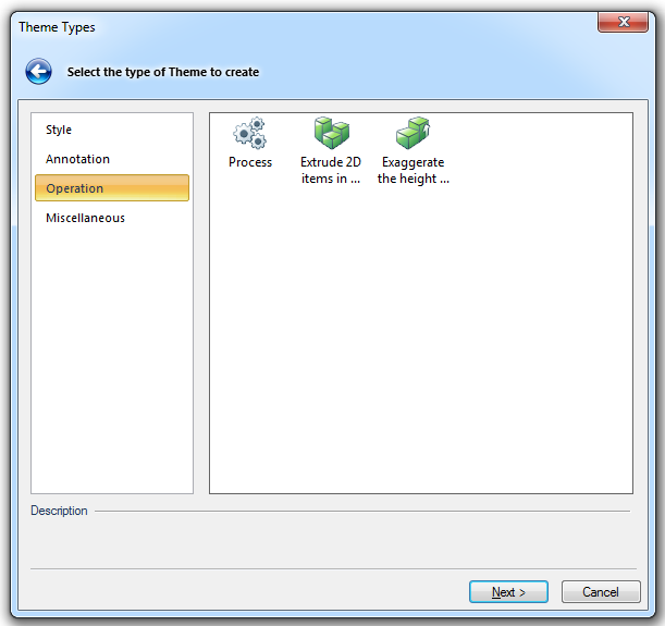
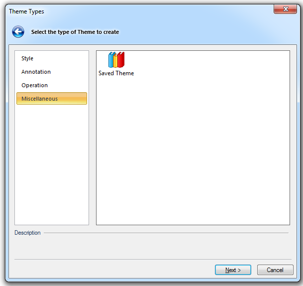
Themes add items such as bar charts, pie charts, etc., to a map to provide more information to the user. Use Add Theme [Home-Map] to add a theme.
The Theme Types are grouped as follows:
For further information see Themes
You can use Print [File-Print] to print the view in the current (active) window to any connected printer. You should pan and zoom first so that the view in the Map Window is the view you want reproduced. However, this will not have any title, key or legend etc. To include these features you need to use either Print Template [File-Print Template] or Quick Print Template [File-Print Template].
![]()
Quick Print Template allows you to select a Template, place it, change the scale and define a view rotation.
Print Template allows you to customise the Template further as you use it, adding any or all of the following features:
Both Quick Print Template and Print Template allow you to select from a range of print templates grouped into the following styles:
There are a number of dialogs to step through when using Quick Print Template or Print Template. The final dialog for each is:
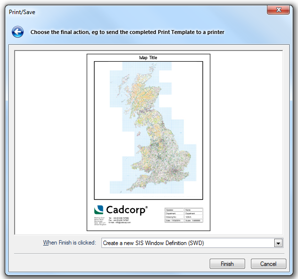
This allows you to either:
For further information see What is a Print Template?
For more general information see The SIS User Interface
Click to return to www.cadcorp.com
© Copyright 2000-2017 Computer Aided Development Corporation Limited (Cadcorp).
.png)